
Robot Dock and Charger Commissioning: Tolerances, Load and the Downtime They Cause
At a glance: Dock failures stop more fleets than navigation faults do. The alignment and flatness tolerances to measure and record, the electrical budget of a shared charging bay at peak load and summer temperature, and a five-step commissioning routine that exercises the fault paths before 02:00 does.
Ask a fleet operator what stops their robots and the answer is rarely navigation. It is the dock. A machine that navigates a busy atrium perfectly can fail to charge because the floor settled 4 mm under one corner of the charging plate, or because the contacts have pitted after 900 cycles and are now making contact through a coat of oxide. The dock is the only part of the system that is installed by a third party on a floor that keeps moving, and it is the part nobody puts in the acceptance procedure. This article covers the tolerances that actually matter, the electrical budget a charging bay needs, and a commissioning routine that catches the failures before they become nightly ones.
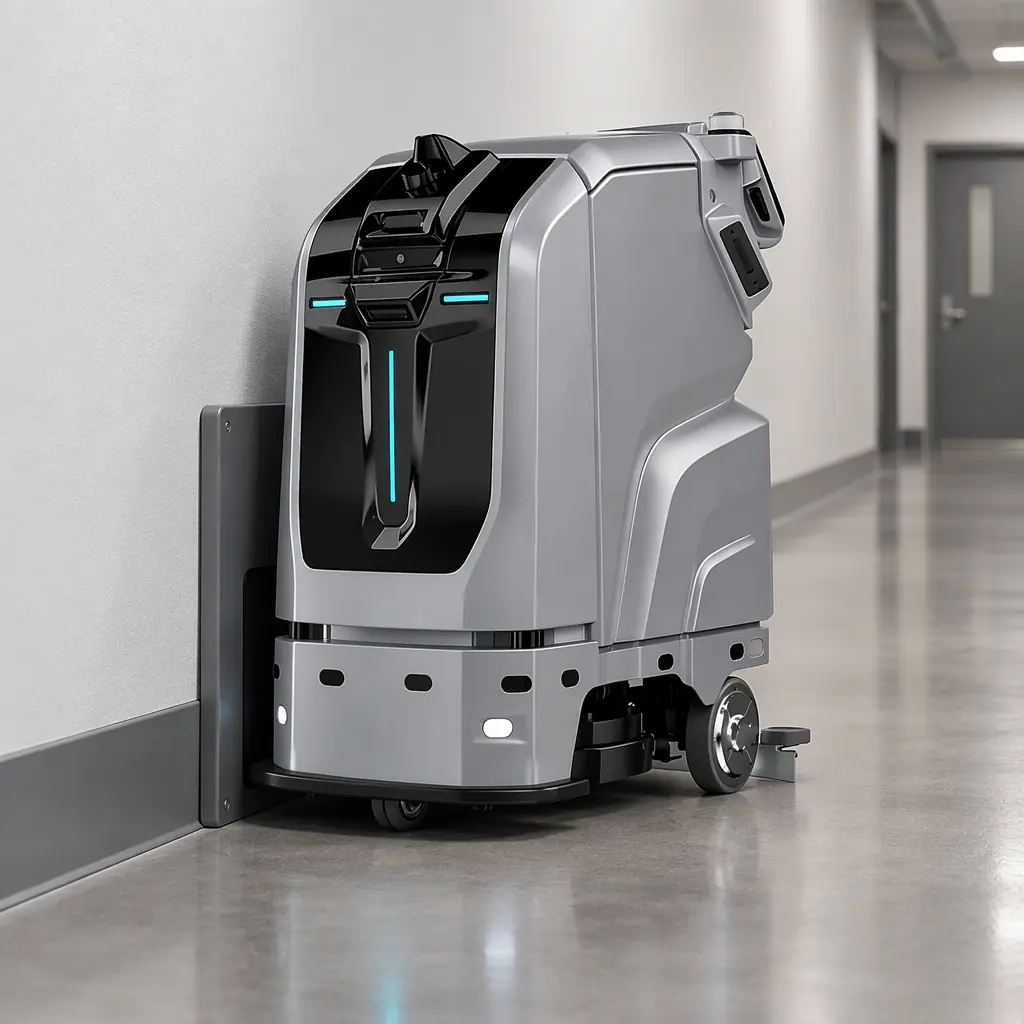
Why the Dock Fails Before the Robot Does
Four properties of the installation make the dock the weakest link, and none of them is a robot defect.
The alignment tolerance is set by the contacts, not by the camera. A docking routine using a fiducial or a reflector can find the dock from a metre away and still fail, because the last 30 mm is a mechanical problem. Lateral and angular alignment at contact are the numbers to specify; a docking camera's reported confidence says nothing about whether the contacts will seat.
The floor moves. A newly poured or freshly levelled floor settles, coatings wear through, and a plate fixed to a slab that has cured for six months sits differently from one fixed on day one. A dock installed to tolerance on handover and never re-checked is a dock installed to tolerance once.
Service wear is asymmetric. The approach path produces uneven erosion of the plate and the contacts, and a fleet that always approaches from the same direction wears one side faster than the other. The alignment that was centred at commissioning drifts away from centre over a few thousand cycles.
The dock is a shared resource with a queue. Two robots assigned to one dock create a waiting problem and an arbitration problem, and the arbitration is where the "docked but not charging" state appears.
A dock failure is also the most expensive kind of failure per minute, because a robot that cannot charge cannot be dispatched, so a failed docking at 22:00 can remove a machine from the entire night shift.
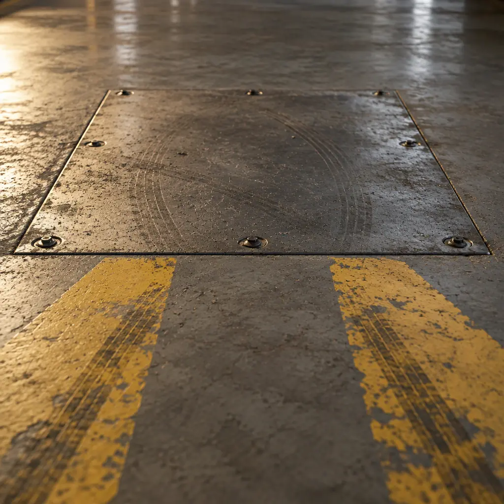
The Tolerances to Write Into the Installation Document
These are the values an installer needs and a buyer should insist on seeing measured, not assumed. Where a specific value is not published by the manufacturer, the discipline is the same: state a number, measure it, record it.
| Parameter | What to specify | How to verify | Consequence if missed |
|---|---|---|---|
| Lateral alignment at contact | Centred within a few millimetres of the nominal axis at the moment of contact | Gauge plate or a marked reference line, checked on five consecutive dockings | Contacts seat on the edge of the pad, heating and pitting begin within weeks |
| Angular alignment | Robot axis within a small angle of the dock axis, stated in degrees | Angle block or laser reference at the plate | Partial contact, intermittent charging, slow charge detection faults |
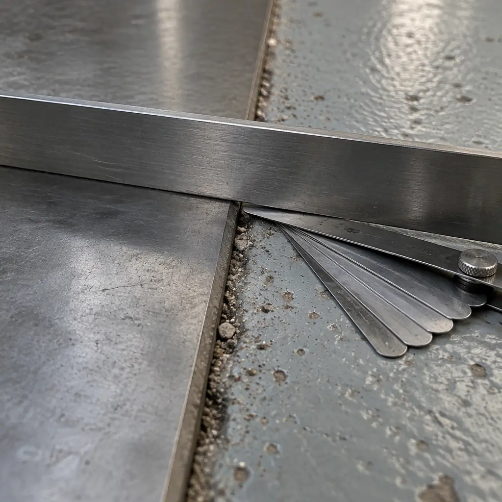
| Floor flatness under the plate | Flatness measured across the plate footprint, not the aisle | Straight edge and feeler gauge at four orientations | Rocking chassis, contact bounce, docking retries |
| Plate height versus floor | Plate surface flush with the surrounding floor, with no lip in the approach | Straight edge across the joint | Approach impact, drive wheel slip, misalignment accumulation |
| Contact force and wipe | Enough force for a stable connection, with a small wipe over the pad | Manufacturer's gauge or documented spring specification | Oxide film builds up, resistance rises, charge current falls |
| Clearance behind the plate | Room for the chassis to overshoot slightly without touching a wall or kerb | Physical measurement with the robot docked | Bumper contact triggers an undock, producing a dock-fail loop |
The angular and lateral values are the two most useful numbers on the sheet because they are the ones that drift, and the drift is measurable: a docking that needed one attempt at commissioning and needs two or three a month later is a dock that has moved out of tolerance, not a robot that has become less capable.
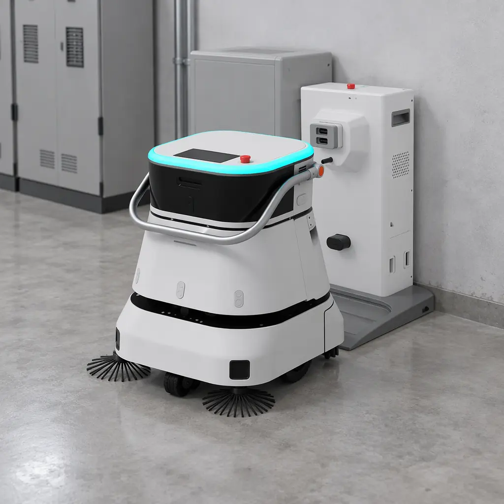
The Electrical Budget of a Charging Bay
Sizing the electrical side is arithmetic, and the arithmetic is usually done for the average rather than the peak. Start from the charge rate and multiply forward.
Charger input power. A charger delivering 60 A at 29.2 V into the battery is 1,752 W at the pack, and after conversion losses the input draw is higher, typically 1.9 to 2.1 kW for a well-designed unit and less efficient below 85% state of charge. Four such chargers on one circuit is a peak load near 8 kW, which will trip a modest shared circuit if it was sized for lighting.
Loaded voltage drop. Cable length and gauge matter more than most site surveys assume. A 30 m run of undersized cable feeding a bay at 60 A produces a measurable drop at the charger input, and a charger that sees low input voltage compensates by drawing more current, which worsens the drop. Measure the voltage at the charger terminals with the bay fully loaded, not at the panel.
Simultaneous start. If all chargers in a bay energise at the same time, the inrush can trip a breaker sized only for the steady load. Staggering charge starts by a few minutes is free and removes the whole failure mode.
Thermal headroom. A plant room at 35°C reduces the continuous rating of the chargers and the available capacity of the packs. The bay that works in winter can throttle in July, and a throttled charge is a robot with a shorter next shift.
The practical rule: size the bay for the number of robots that could dock simultaneously, at the worst ambient temperature of the year, and measure the input voltage under that full load rather than calculating it.
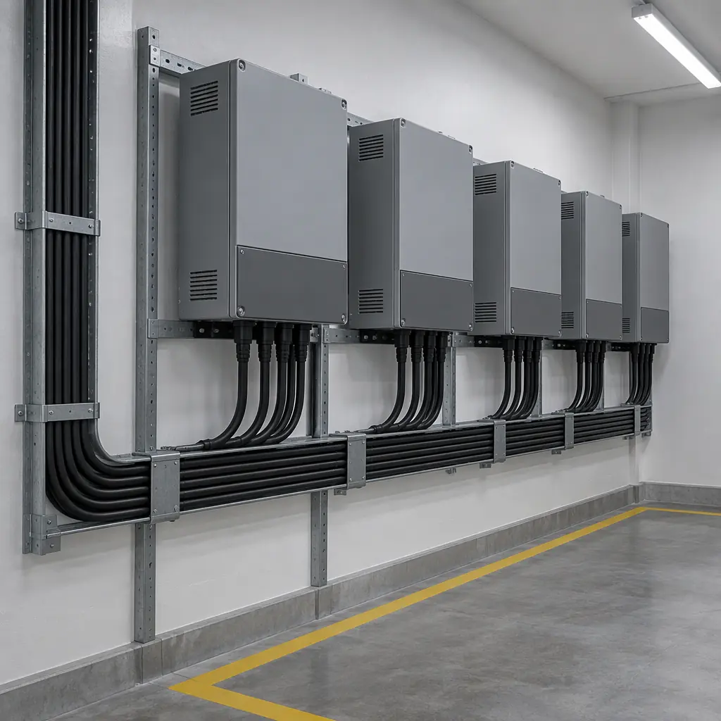
Commissioning the Dock: Five Steps That Catch Most Failures
Dock commissioning is short if it is done in the right order. Doing it in the wrong order, typically docking first and measuring later, hides the failures that only appear under load.
- Survey the floor before fixing anything. Measure flatness and level across the full footprint and the approach path. If the floor fails, the dock will fail, and no amount of re-levelling the plate fixes a slab that is not flat.
- Fix the plate to the specified tolerances and record the measured values. Lateral offset, angle, height and flatness, with the tool used. Photograph the setup; the photograph is what a later dispute turns on.
- Run ten consecutive manual dockings and record the attempts per success. Ten for ten is the target. Any retry here is a tolerance problem, not a software problem, and it will get worse, not better.
- Measure the electrical state under load. Input voltage at the charger terminals with every charger in the bay energised at once, charge current at the pack, and the temperature of the contacts after twenty minutes. Contact temperature is the cheapest early warning of a high-resistance joint.
- Test the fault paths deliberately. Deliberately misalign the plate, block a contact, remove power during a charge, and confirm the robot reports the correct fault and recovers without a technician. A fault path that has never been exercised is a fault path that will be discovered at 02:00.
Then put the dock on a maintenance schedule: a quarterly visual and measurement check, and a re-measure of lateral alignment after any floor work, coating renewal or change to the route that alters the approach direction. Twenty minutes a quarter per dock is the difference between a fleet that charges and a fleet that needs an attendant.
What AOMAN Provides and What It Does Not
AOMAN supplies the dock's mechanical specification: contact geometry, the alignment window the chassis can tolerate, plate dimensions and fixing pattern, required clearance, the charger's input specification and the recommended circuit sizing per unit. Where a site has an unusual floor condition, our engineering team will review the survey before the plate is fixed rather than after.
What we do not do is certify the installer's floor or the building's electrical installation. The flatness measurement, the circuit loading and the sign-off on the electrical side belong to the operator and their contractor. What we ask in return is that the measured values are recorded, because the single most useful document for a dock that misbehaves in month nine is the sheet that says what it measured in month one.
The short version: specify alignment and flatness as measured numbers, budget the bay for simultaneous peak load and summer temperature, commission in the order above, and put the dock on the same maintenance calendar as the robot.

Get a Quote
Tell us about your space and workload, we reply within 24 hours.