
Service Robot Battery Fire Safety and Charging-Room Design
At a glance: A single cleaning robot charges quietly in a corridor and nobody worries. A fleet of twenty charging overnight in a basement plant room is a lithium battery storage installation, and it brings fire code, room design, and detection obligations that the robot datasheet does not mention. This guide covers the fire risk profile of service robot packs, the room-design rules that follow from it, and the compliance checks a facility manager should demand before the first dock is bolted to the floor.
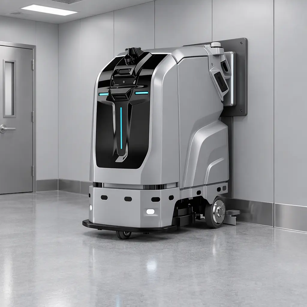
The Fire Risk a Robot Fleet Actually Introduces
A service robot fleet is a distributed lithium battery installation. Each robot carries a pack of a few kilowatt-hours, each dock contains charger electronics, and the fleet charges in a room the building was not necessarily designed to treat as a battery location. The risk is not hypothetical and it is not the same as the risk from a phone or a laptop, because the quantity of stored energy per square metre in a charging bay is far higher than in an office.
The failure mode to design against is thermal runaway. In a lithium cell this is a self-sustaining rise in temperature: once a cell exceeds a threshold, internal reactions generate more heat than the cell can shed, which propagates to neighbouring cells. How violent that propagation is depends on cell chemistry. Lithium iron phosphate (LFP) chemistry, common in service robots for its cycle life and thermal stability, has a higher onset temperature and a milder propagation than the nickel manganese cobalt (NMC) chemistry used where energy density matters more. A buyer choosing chemistry is also choosing a fire-risk profile, which is one reason the chemistry decision in battery pack specification is not only about runtime.
Four conditions make a robot charging area riskier than a well-managed battery room, and each is addressable. Charging generates heat, so a room with poor airflow concentrates it. Robot packs are charged by non-technical cleaning staff who have no reason to notice a swelling pack. Docks are often installed in plant rooms and storage corridors with no detection and no suppression. And mixed fleets may hold packs of different ages and chemistries charged side by side, so a fault in one has more neighbours to propagate to. The guide is organised around closing those four gaps.
The Standards That Define a Compliant Charging Room
The applicable rules depend on the jurisdiction, but a small set of documents recurs across markets and gives the facility manager a common language with the authority having jurisdiction (AHJ), the local fire or building official who signs off on the installation.
| Document | What it addresses | Why a robot fleet cares |
|---|---|---|
| NFPA 855 (US) | Installation of stationary energy storage systems | Sets separation, detection, and suppression expectations for battery rooms |
| UL 9540A (US) | Test method for thermal runaway propagation | The propagation data fire engineers use to size protection |
| UL 1973 / UL 2271 | Battery system and light electric vehicle battery safety | Product-level safety certification for packs |
| IEC 62619 | Safety of industrial lithium cells and batteries | International product baseline for robot-scale packs |
| Local fire code (varies) | Occupancy, egress, ventilation, sprinkler | The rule that actually governs the room, wherever it is |
Two points cut across all of them. First, a robot charging bay is frequently treated as "equipment" rather than as battery storage, which lets installations proceed without the review they need; the correct move is to describe the installation to the AHJ in energy terms (kilowatt-hours stored, chemistry, maximum charge power) and ask what classification applies. Second, the product certifications on the robot datasheet (UL 2271, IEC 62619 and similar) verify the pack as a product; they do not approve the room it charges in. Those are separate approvals and both are needed. The product-side certification that gates shipping is a different exercise, covered in battery certification and transport.
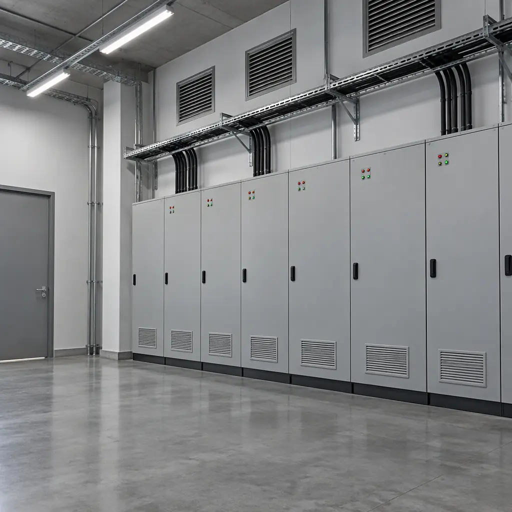
Designing the Charging Area
The room design turns the risk assessment into physical provisions. Whether the fleet charges in a dedicated room or in marked bays on a service corridor, eight design decisions define how safe the installation is and how easily it passes review.
- Separation. Keep charging away from combustibles, exits, and occupied space. A charging bay against a wall shared with a stairwell is the wrong place for twenty packs.
- Non-combustible construction. Walls, ceilings, and finishes in the charging area should be non-combustible, so a fire has nothing to feed on while responders arrive.
- Egress. The charging area must not be inside the only exit path from the room; a fire there should never trap anyone.
- Ventilation. Thermal runaway releases flammable and toxic gases. Even LFP packs vent, so the room must clear gas rather than trap it.
- Detection. Smoke and heat detection in the charging area, ideally linked to the building fire alarm, so a fault is seen at the point of origin rather than by smell on another floor.
- Suppression. The protection strategy (sprinkler, water mist, clean agent, or monitored containment) follows from the propagation data and the AHJ's view; it is not the robot vendor's decision.
- Dock spacing. Physical gaps between charging positions limit cell-to-cell and pack-to-pack propagation, and give a responder room to act.
- Isolation. A means to de-energise the charging circuits from outside the area, so the installation can be shut down before anyone enters.
None of these eight is exotic, and together they describe a room an insurer and a fire officer will recognise. The design work belongs in the facility plan at the same stage as the electrical supply, not after the robots arrive. The power side of that planning, including the electrical capacity a fleet needs, is treated under fleet charging infrastructure and power planning.
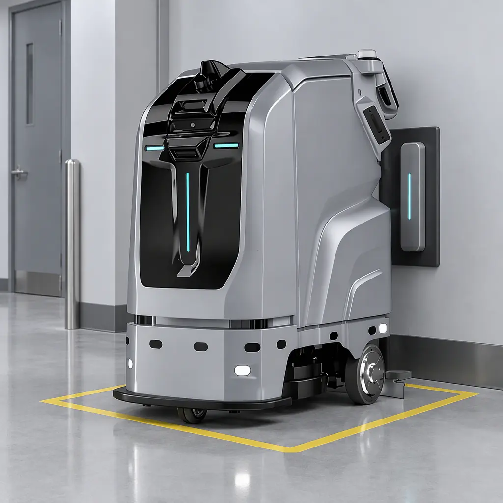
Detection, Suppression and the Realistic Response
The uncomfortable truth about lithium fires is that suppression buys time, not extinguishment. A pack in full thermal runaway generates its own oxygen and its own heat, so the goal of the protection system is to contain propagation, limit smoke, and hold the fire until the cells have consumed their energy, while people evacuate safely.
That changes the priority order. Early detection matters more than aggressive suppression, because the earlier a fault is caught (ideally at the swelling or first vent stage), the smaller the event. Once a pack is fully involved, the correct response in most cases is to evacuate, isolate the circuits, and let the fire service manage it, with the containment design having limited the damage. A facility that expects a sprinkler head to put a lithium fire out the way it puts out a paper fire has the wrong mental model, and the exercise should be documented so everyone knows the plan.
| Protection layer | What it does | What it does not do |
|---|---|---|
| Smoke / heat detection | Gives early warning at the point of origin | Cannot stop a cell already in runaway |
| Sprinkler | Cools surrounding material, limits spread | Does not extinguish a lithium pack in runaway |
| Water mist | Cooling with less water damage than sprinkler | Still a containment tool, not an off switch |
| Clean agent | Protects surrounding equipment from fire and smoke | Limited effect on the runaway cell itself |
| Containment / spacing | Limits propagation between packs | Requires the installation to be designed for it up front |
The response plan should also cover charging discipline, because a large share of incidents happen during or shortly after charging. Charging in a monitored area rather than an unattended corner, charging during occupied hours where practical, and stopping charging of any pack that is visibly swollen, hot, or reporting abnormal BMS data are low-cost controls that reduce the probability of the event the room is designed to survive.
What the Robot Vendor Should Provide
The facility manager buys the room, but several inputs come from the robot vendor and should be requested in writing before the installation is designed.
- Pack chemistry and energy. The kilowatt-hour rating and chemistry (LFP or NMC), so the installation can be classified and the risk assessed.
- Product certifications. The UL 2271, IEC 62619, or equivalent certificates for the pack and dock, for the permit submission.
- Charging power and profile. Maximum charge rate and the charge curve, so the electrical supply and heat load are sized correctly.
- BMS fault reporting. Whether the BMS flags over-temperature, over-voltage, and cell imbalance, and how that alarm reaches the operator.
- Thermal runaway data. Where available, UL 9540A or equivalent test data, which the fire engineer can use instead of assuming worst-case propagation.
- Emergency isolation. How to shut down charging safely and what the safe handling procedure is for a suspect pack.
This documentation is the difference between a permit submission that proceeds and one that stalls on a question nobody can answer. It also connects the fire-safety design to the wider compliance picture, since the safety and marking obligations for a robot deployed on a public floor are laid out separately in safety standards and compliance, and the health data the BMS exposes feeds the replacement plan described under battery health monitoring.

The Takeaway
A robot fleet is a lithium battery installation, and treating the charging area as ordinary equipment storage is the mistake that turns a manageable risk into an incident. Design the room for separation, non-combustible construction, ventilation, detection, and containment; describe the installation to the authority having jurisdiction in energy terms; and get the pack certifications and thermal-runaway data from the vendor before the docks are installed. The fire risk from a service robot fleet is real and well understood, which means it can be designed out. What cannot be designed out is the risk of not designing for it at all.

Get a Quote
Tell us about your space and workload, we reply within 24 hours.