Robot Battery Thermal Runaway: Assessing and Reducing Fire Risk Before a Fleet Order
At a glance: A service robot battery fire is a cell-level event that becomes a building-level event in about ninety seconds, because the charge collects in a sealed pack under a plastic housing inside an occupied space. Suppliers answer the risk question with a chemistry name and a certificate, which is not an engineering answer. This guide sets out what actually drives propagation, the four numbers that separate a low-risk pack from a high-risk one, the placement and monitoring measures that buy response time, and the evidence a buyer should demand before a fleet order.
The enquiry usually arrives after an incident elsewhere: a scooter pack in a lobby, a vacuum in a service corridor, a phone in an aircraft cabin. The facility manager asks the robot supplier a single question, can this catch fire. The answer comes back as LFP, certified, no problem, and the conversation stops. Nothing has been assessed. LFP is safer than NMC on several axes and is not immune to a thermal event, and a certificate for the cell says nothing about the pack, the charger, the dock or the room the robot sleeps in.
What Actually Propagates a Battery Fire
A single cell venting is survivable. A pack in thermal runaway is not, and the difference is propagation: the energy released by one failing cell heating its neighbours above their own runaway threshold. Four factors decide whether a fault stays a fault or becomes a fire: the energy stored in the pack, the spacing and thermal coupling between cells, the pack's ability to vent combustion gases away from its neighbours, and what the surrounding enclosure and room do with the resulting heat and gas.
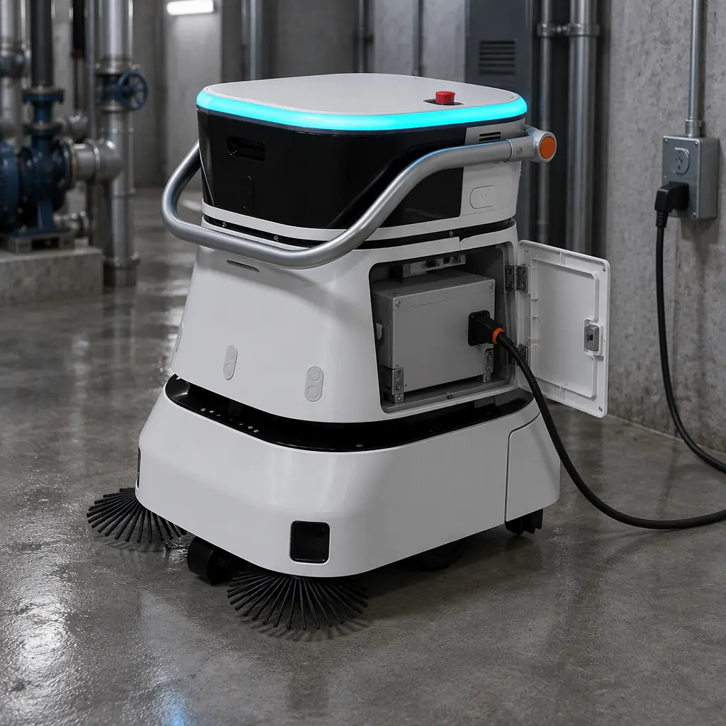
- Energy is the denominator for everything. A 25.6 V 100 Ah pack stores about 2.5 kWh. The same nominal capacity in a 51.2 V pack stores 5.1 kWh, and a heavy-lift AMR pack can reach 15 to 20 kWh. Two packs of identical chemistry at different energy levels are different hazards and should never be covered by one risk statement.
- Cell spacing and coupling set the trigger energy. Cells packed tightly with no thermal barrier pass heat to a neighbour in seconds. Cylindrical cells with spacing, mica or aerogel barriers between groups, and a metallic heat sink that spreads heat away from the fault are the standard mitigations, and they are visible in a pack teardown or an internal construction drawing.
- Venting direction decides who gets hurt. A pack that vents into its own housing pressurises the housing and drives hot gas through every gap. A pack with a designed vent path directs gas away from cells, away from the operator's face height, and out of the robot chassis.
- The room is part of the system. A charging room with combustible shelving, cardboard storage and no detection converts a pack event into a contents fire within minutes. The same event in a concrete room with detection, an isolated charging bay and a clear egress path is a cleanup.
The Four Numbers That Classify Pack Risk
Most of the argument about chemistry can be replaced by four figures that any competent pack supplier already has on file. Ask for them in writing; a supplier who cannot produce them has not modelled the pack.
| Figure | What it measures | Low-risk indication | Why it matters |
|---|---|---|---|
| Total pack energy, kWh | Nominal voltage × capacity | Under 3 kWh for indoor public-facing units | Sets the fire load and whether the space needs a dedicated charging room |
| Cells per series string and pack topology | Electrical arrangement | Documented string count with per-string fusing | An unfused parallel string turns one cell fault into a whole-bank event |
| Barrier and spacing spec | Thermal isolation between cell groups | Named barrier material and thickness between groups | The single most effective propagation control after energy reduction |
| Vent path and enclosure rating | Where gas goes under fault | Defined vent outlet, IP-rated housing, no re-entry into the pack | Determines operator exposure and whether the chassis contains or channels the event |
A fifth number, peak fault current at the pack terminals, is worth having for the charger design. A 48 V 200 Ah pack can deliver several thousand amps into a short before protection operates, and a dock or charger that cannot clear that fault safely is a second ignition source.
Chemistry by Risk Profile, Not by Marketing
Chemistry choice changes the threshold, not the existence of the risk. The comparison below is about behaviour under abuse, and it assumes a competent BMS in every case.
| Chemistry | Nominal cell voltage | Thermal runaway onset | Behaviour under abuse | Fit for indoor public space |
|---|---|---|---|---|
| LFP | 3.2 V | Roughly 250 to 270 °C | Vents, may smoke heavily, propagation slower and easier to interrupt | Preferred for lobby, retail and healthcare robots |
| NMC | 3.6 to 3.7 V | Roughly 150 to 210 °C, falling with state of charge | Vigorous venting, higher heat release, faster propagation | Acceptable with barriers, spacing and a dedicated charging room |
| LTO | 2.3 to 2.4 V | Highest of the three | Very hard to drive into runaway; lowest abuse sensitivity | Best abuse tolerance, lowest energy density, higher cost per kWh |
| Lead acid | 2.0 V | Not applicable in the same sense | Hydrogen evolution on overcharge, acid spill risk | Legacy platforms only |
Two practical notes sit under that table. First, state of charge dominates the NMC numbers: a pack at 100 percent state of charge in a warm dock is materially more reactive than the same pack at 40 percent, which is the argument for storage and overnight parking at partial charge rather than a full top-up. Second, the energy density advantage of NMC is real and is why heavy-lift and long-shift platforms still use it; the honest answer to a buyer is not that one chemistry is safe and the other is not, but that the pack, the charger and the room must be designed for the chemistry that was chosen.
Where Robots Fail in Real Buildings
Field incidents cluster around a small number of causes, and most of them are installation errors rather than cell defects.
- Charging in an unmonitored space. A robot left to charge overnight in a plant room, storage closet or under a stair is the most common configuration in a first deployment, and the worst one. Nobody is present, detection is absent and the space is usually full of combustibles.
- Mismatched charger. A replacement or third-party charger with the wrong CV setpoint overcharges a pack that has no independent over-voltage cutout. Charger and pack must be specified together, and the charger's voltage tolerance belongs in the acceptance test.
- Mechanical damage from dock alignment. Repeated misalignment on a worn dock stresses the pack housing and the connector. A cracked housing that admits cleaning water is an insulation fault waiting for a shift.
- Water ingress in cleaning robots. A scrubber operates in exactly the environment that destroys pack insulation. IP rating on the pack, not just the robot, is the relevant specification, and it must survive the actual wash-down practice, not the datasheet's test condition.
- Fast charging without a thermal interlock. Charge rate that ignores pack temperature, or a BMS that reports temperature but does not curtail current, gives the pack no way to protect itself in a hot plant room in summer.
Buying Response Time: Placement, Detection and Isolation
The engineering goal is not to make a fire impossible. It is to make the interval between fault and detection long enough for a response, and to make sure the response does not require entering a smoke-filled room.
| Measure | Effect | Practical specification |
|---|---|---|
| Dedicated charging bay | Separates fire load from storage and from egress | Non-combustible surfaces within 3 m, nothing stored in the bay, clear route to an exit |
| Off-hours partial charge | Reduces state of charge during unattended hours | Target 50 to 70 percent overnight, top up before shift |
| Smoke or gas detection in the bay | Converts an undetected event into an alarm within minutes | Detector linked to the building alarm, not a local buzzer |
| Remote pack telemetry | Surfaces cell temperature and voltage spread before a fault | Per-cell-group temperature and delta logged to the fleet platform with an alert threshold |
| Isolation and contactor | Removes the energy source from the fault | Pack-level contactor that opens on over-temperature, independent of software |
| Documented response procedure | Prevents the wrong action under pressure | Named isolation point, no water on a live pack, evacuation trigger, supplier 24h contact |
Detection is where most deployments underinvest, because it is a building cost rather than a robot cost. A pack that fails at 02:00 in a plant room with no detection is discovered by staff arriving at 07:00, by which point the room is involved. The same pack with a detector linked to the fire panel is a controlled event with a named response. Buyers should treat charging-room detection as part of the deployment scope, on the same footing as the dock.
Telemetry is the cheaper half of the same measure and it works before ignition. Cell-group temperature spread is the most useful single indicator: a pack whose hottest group sits consistently 6 to 8 °C above the others is telling you something about a connection resistance or a cooling path, and that signal is available weeks before a fault. What the data contract behind those alarms should contain is set out in the battery telemetry data contract guide.
The Evidence a Buyer Should Ask For
- UN 38.3 test summary for the pack as shipped, not for a sample cell. Transport documentation is the minimum, not the ceiling.
- IEC 62133-2 or equivalent cell and pack abuse test report, with the abuse cases named: overcharge, external short, crush, thermal abuse, and the result of each.
- An internal construction drawing showing cell spacing, barrier material, vent path and per-string fusing.
- BMS specification covering over-voltage, over-current, over-temperature and the independent hardware cutout, with the thresholds written down.
- Charger and pack compatibility statement with voltage setpoints and tolerance, plus the charge profile at 0, 25 and 40 °C ambient.
- A written statement of the pack's behaviour in a single-cell thermal event, not a claim that no such event can occur.
None of these documents tells a buyer the risk is zero. Together they tell a buyer whether the supplier has modelled the risk at all, which is the only thing that separates a designed product from an assembled one. The transport and certification side of the same paperwork is covered in the battery certification and transport guide, and the room-level code requirements in the charging-room design guide.
Assessing the Risk in One Afternoon
A facility team can produce a defensible risk position for an existing fleet without a consultant, using four steps:
- List every place a robot charges, with the pack energy of the unit and whether the space is attended, detected and free of combustibles.
- Rank the sites by energy multiplied by occupancy: a 5 kWh pack in an unattended storeroom outranks a 2.5 kWh pack in a staffed lobby.
- Fix the top three sites with placement, partial-charge overnight policy and detection. These are low-cost measures and they remove most of the residual risk.
- Collect the six documents above for every pack in the fleet and note which suppliers cannot produce them. That list is the procurement conversation for the next order.
How AOMAN Addresses Battery Safety
AOMAN specifies packs, chargers and docks together for the D1 delivery, C1 and C2 Pro cleaning and G1 reception platforms, which means the charge profile, the BMS thresholds and the dock alignment are one design rather than three purchases. Pack energy, chemistry, barrier construction and vent path are quoted per platform against the duty cycle, and buyers deploying into public buildings can request the cell and pack abuse documentation, the construction drawing and the charger compatibility statement with the quotation. Platform details are on the products page, and the charging and fleet architecture is described on the technology page.