
RS485 Service Robot Batteries
At a glance: Most RS485 battery specifications fail at integration, not at the cell. The pack arrives with the right energy and the wrong baud rate, an unbalanced A/B pair that works on the bench and fails at twelve metres, or a register map that exposes voltage and current but not state of charge. This guide sets out the nine fields a robot battery specification actually needs, the arithmetic that turns a chemistry choice into a voltage and capacity line, and the acceptance tests to run before a fleet order is placed.

Why RS485 Batteries Fail at Integration, Not at the Cell
An RS485 battery fails in the field for four reasons, and only one of them is electrochemical: wrong baud and framing, a register map that omits state of charge, missing galvanic isolation on a high-voltage pack, and multi-drop wiring that was never terminated. The cell is usually the most reliable part of the assembly. The specification document is the weakest, because battery suppliers and robot integrators write it in different vocabularies.
A pack supplier quotes energy in watt-hours, cells in series and parallel, a continuous discharge rate and a cycle count. A robot integration team needs a message rate, a register address for every telemetry value it displays, a bus topology that tolerates a 15-metre harness down the chassis, and a defined behaviour when the pack goes offline mid-shift. Neither document is wrong. They simply describe the same object at two levels, and the gap between them is where a fleet acceptance test fails in week three.
The commercial consequence is specific. When a pack's communication layer has to be changed after tooling, the change is not a firmware patch; it is a new board revision inside the pack, a new certification sample if the pack is transport-certified, and a firmware release on the robot side. Buyers who get the nine fields below right in the enquiry avoid that cycle entirely.
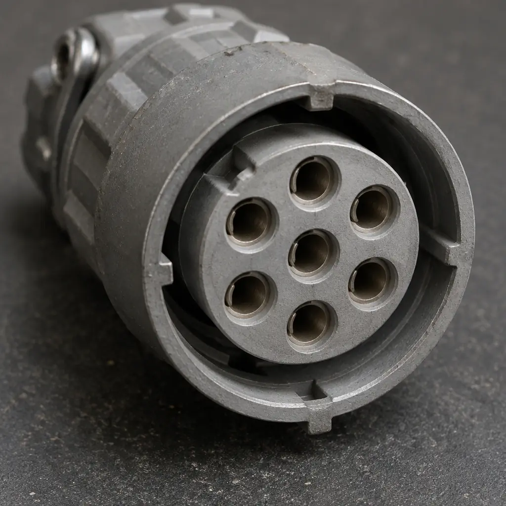
The Nine Fields an RS485 Battery Specification Needs
The list is short enough to fit on one page and complete enough that a compliant pack can be integrated without further negotiation. Each field exists because its absence has a known failure mode.
| Field | Typical value | What goes wrong if it is omitted |
|---|---|---|
| Nominal voltage and chemistry | 24 V LFP, 48 V LFP, 25.6 V NMC | Charger and dock rated against the wrong curve; charge acceptance mismatched at high state of charge |
| Capacity and usable energy | 60 Ah / 1.54 kWh nominal, 80 percent usable | Shift sizing done on nameplate energy, runtime falls 20 percent short |
| Continuous and pulse discharge | 1C continuous, 2C for 10 s | Brownout on brush-motor inrush or lift start |
| Physical layer | Half-duplex two-wire, 9600 or 19200 baud, 8N1 | Integrator assumes 115200; every frame is read as a checksum error |
| Protocol and register map | Modbus RTU, documented register table | Fleet dashboard can show voltage but not state of charge or cycle count |
| Isolation and common mode | Galvanically isolated transceiver, 1 kV | Ground offset across a long chassis harness corrupts frames under motor load |
| Bus topology and termination | Daisy-chain, 120 ohm at both ends, failsafe bias | Star wiring with no termination works on the bench, fails at 12 m |
| Addressing and identity | Configurable 1 to 247, unique per pack, serial readable | Two packs on a swap station collide; telemetry attributed to the wrong unit |
| Protection and safe-state | Over/under-voltage, over-current, over-temperature, contactor open on fault | Pack keeps supplying after a fault; no defined limp-home behaviour |
Nine fields, one page. The two that generate the most support tickets are the physical layer and the register map, and both are cheap to specify and expensive to retrofit.
Voltage and Capacity Arithmetic Before You Send the Enquiry
Chemistry first, because it sets the voltage envelope. LFP sits at 3.2 V nominal per cell, NMC at 3.6 to 3.7 V, LTO at 2.3 to 2.4 V. A 24 V LFP pack is therefore 8 cells in series, giving 25.6 V nominal and 29.2 V at full charge; a 48 V LFP pack is 16 cells, 51.2 V nominal. NMC reaches roughly the same nominal voltage with 7 cells in series at 3.7 V, which is why an NMC pack and an LFP pack can both be called 24 V while behaving completely differently at the top of the charge curve.
Capacity follows from the shift. The sequence is: measure the real duty cycle in hours of motion, apply the pack's own average draw in the application rather than the datasheet's continuous rating, add the idle and standby draw for the unworked portion of the shift, then divide by usable energy, not nominal energy.
| Step | Worked example, compact scrubber |
|---|---|
| Motion hours per shift | 5.5 h of a 7 h shift |
| Average draw in motion | 620 W (traction, brush motors, vacuum, compute) |
| Standby draw, remaining 1.5 h | 85 W |
| Energy per shift | 5.5 x 620 + 1.5 x 85 = 3,410 + 128 = 3,538 Wh |
| Energy per shift with 15 percent reserve | 4,069 Wh |
| Pack at 80 percent usable depth | 4,069 / 0.80 = 5,086 Wh nominal |
| At 25.6 V nominal | 5,086 / 25.6 = 199 Ah, so a 200 Ah pack, not a 150 Ah pack |
The last line is the one buyers get wrong: sizing on the 80 percent usable depth, the temperature derate and the reserve adds roughly a third to the nameplate number people carry in their heads. The full derivation, including the availability denominator and the charge-acceptance check against the dock window, is set out in the battery pack specification and sourcing guide, along with the sourcing questions that separate a pack assembler from a pack designer.
Ports, Hardware Layers and Bus Rates
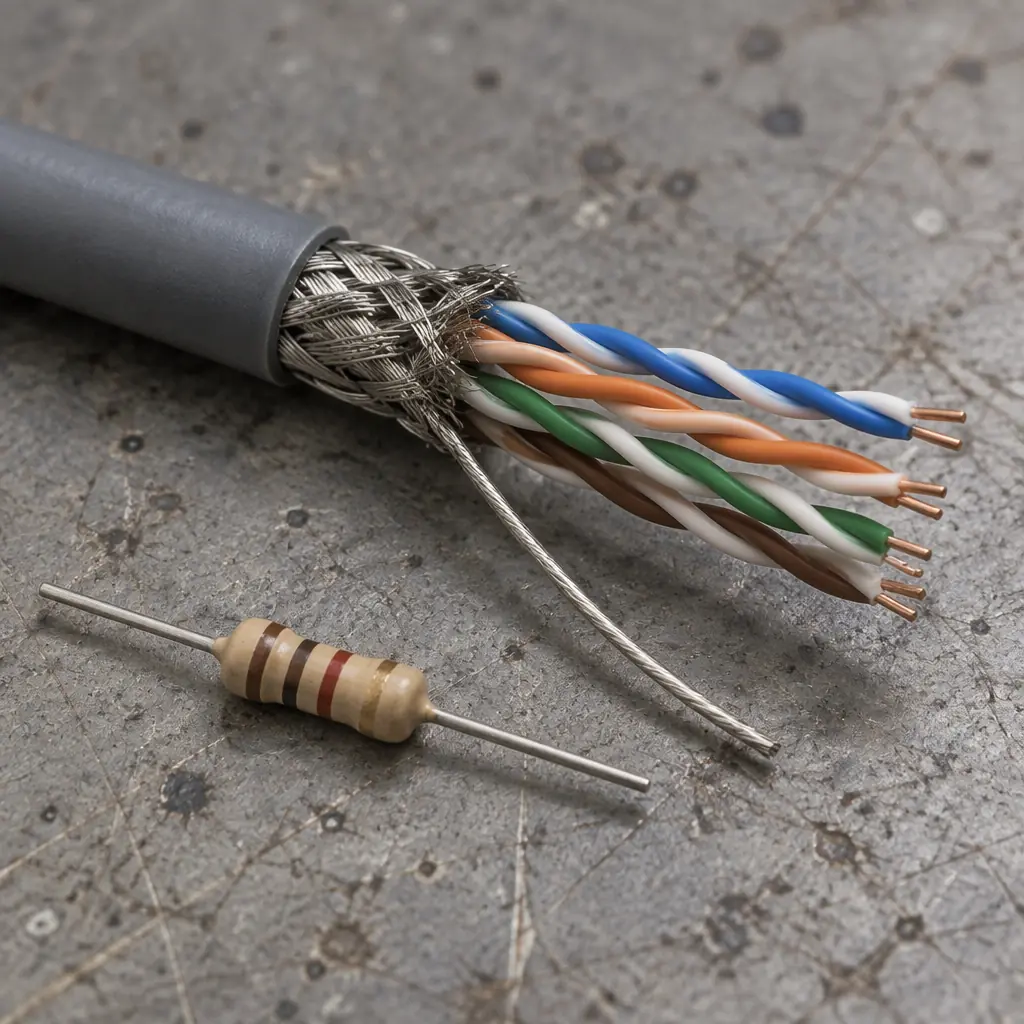
RS485 is a physical layer, not a protocol. Three decisions sit on top of it and each has a default that buyers should override consciously.
- Baud rate and framing. 9600 baud 8N1 is the most forgiving over long harnesses and the most common default in industrial packs; 19200 is common on newer BMS boards; 115200 is offered by some vendors and is a poor choice on an unshielded 12-metre chassis run at high motor noise. Specify the rate rather than accepting whichever the supplier flashed.
- Protocol. Modbus RTU is the default for interoperability, and the register map matters more than the protocol name. If the map is proprietary, the buyer loses the ability to write their own fleet layer without a vendor SDK. The register set worth demanding is covered in the battery communication protocols guide, which also explains where CAN bus is the better answer.
- Topology and termination. Half-duplex two-wire RS485 is a daisy-chain bus. Both physical ends need a 120 ohm termination and the bus needs failsafe biasing so an idle line reads as a defined level rather than noise. Star wiring into a central junction box is the most common topology error: it works at two metres on a bench and fails at twelve metres once the traction motors are drawing current.
A practical wiring specification for a robot chassis names the cable type (twisted pair, shielded, with a drain wire bonded at one end only), the maximum stub length to each pack, the terminator resistor value and where it physically sits, and the shield bonding point. Those four lines prevent most field bus faults.
Modbus Register Map: What the Fleet Layer Actually Needs
A pack that reports voltage and current is not instrumented. The fleet layer that schedules charging, plans battery replacement and bills a service contract needs eight values, and if any of them is missing the integration team will end up estimating it on the robot side.
| Value | Why the fleet layer needs it | Typical JSON field |
|---|---|---|
| State of charge, percent | Charge scheduling, dispatch eligibility, low-SoC alarming | soc |
| State of health, percent | Replacement planning and warranty conversations | soh |
| Cycle count | Warranty gate, residual value, second-life eligibility | cycles |
| Pack temperature, min and max cell | Charge current derating, fire-safety interlock, hot ambient detection | temp_min, temp_max |
| Individual cell-group voltages | Detecting the imbalance that precedes a capacity collapse | cell_mv[] |
| Charge and discharge current limits, as enforced | Understanding why a dock is slow on a hot afternoon | chg_limit_a, dchg_limit_a |
| Protection status flags | Distinguishing a pack fault from a robot fault | faults |
| Pack serial and firmware version | Attributing telemetry to a physical asset after a swap | serial, fw |
What a fleet operator does with these eight fields is a contract question as much as an engineering one: retention window, sampling rate and who may read them. The battery telemetry data contract guide covers the retention and access clauses, and the battery health and replacement planning guide shows how state of health converts into a replacement budget line.
Chemistry, Cell Count and Charge Acceptance at the Top of the Curve
The reason the 24 V label is misleading is charge acceptance. As a pack approaches full, the BMS must reduce current to protect the cells, and the rate at which it must do so differs by chemistry. LFP holds a flat voltage curve and then rises steeply at the very top of charge; NMC rises more gradually and starts tapering earlier; LTO accepts high current almost to full and is the reason fast-charge opportunity docking works at all.
For a fleet that docks for 25 minutes between shifts rather than charging overnight, that difference decides whether one dock serves one robot or two. The chemistry-to-duty-cycle mapping and the energy cost per delivered kilowatt-hour are worked through in the battery chemistry and duty cycle selection guide. The practical reading is that a duty cycle with two or more short charge windows per day should not be specified on chemistry alone; it should be specified on charge acceptance at 80 percent state of charge.
Two pack-level consequences follow. First, cells in series multiply the balancing problem, so a 16-cell 48 V LFP pack needs cell-group monitoring, not just pack-level voltage. Second, the number of parallel strings changes the fault behaviour: a single string drops the whole pack, while two strings in parallel mask a failed string until capacity loss becomes visible in runtime.
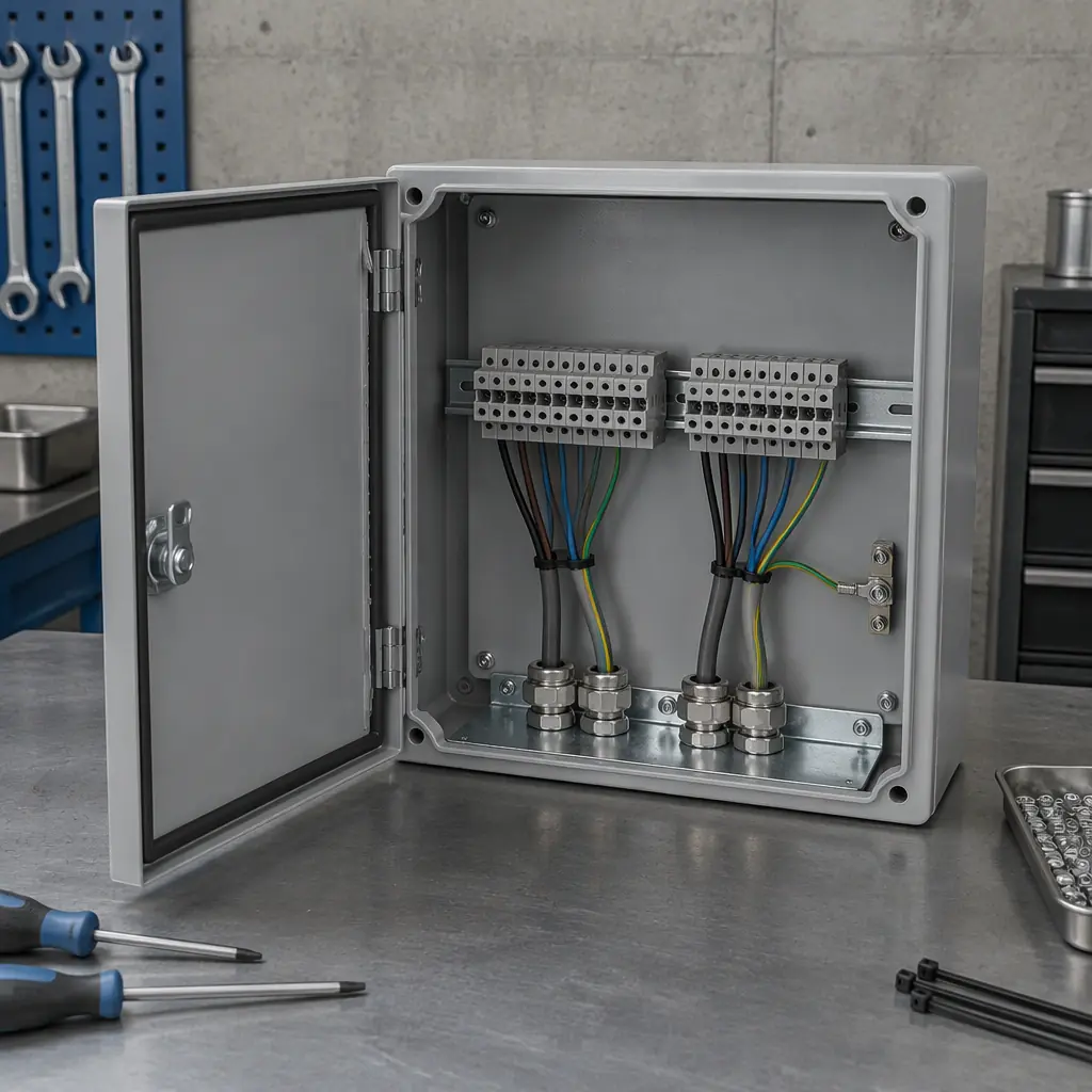
Protection, Isolation and the Safe State
Three protection topics belong in the specification rather than in a later conversation.
Galvanic isolation. On a 24 V pack a non-isolated transceiver often works. On a 48 V or higher pack, or on any chassis where the motor return and the logic ground are separate, ground potential differences across a long harness corrupt frames under load. An isolated transceiver rated at 1 kV removes the problem for a small bill-of-materials cost. If the supply is single-ended and the transceiver is not isolated, the communication fault will appear only when the traction motors are working, which makes it look intermittent and unfixable.
Contactor and pre-charge behaviour. The specification should state what happens on a protection trip: does the pack open its main contactor, does it keep supplying a limited current so the robot can reach a safe position, and how is the fault latched and cleared? A pack that hard-disconnects in the middle of a corridor leaves the robot as an obstacle, which is a safety issue rather than a maintenance inconvenience.
Fire and thermal interlocks. Temperature thresholds that trigger charge inhibition, the sensor placement that detects a hot cell rather than a warm enclosure, and the pack's behaviour in a hot plant room all belong in the same document. The battery fire safety and charging room guide covers the room-side measures that complement pack-side protection.
Acceptance Tests Before a Fleet Order
Nine fields on a page are a specification; the tests below are what turn it into a purchasing decision. Every one of them can be run in a day on a single sample pack and a laptop.
- Frame error rate at distance. Run a polling loop at the specified baud over a 12-metre harness with the traction motors loaded, and count timeouts over 10,000 frames. Under 0.1 percent is a working bus; anything that only passes on a short bench cable is not.
- Register completeness. Read every register in the map and confirm all eight fleet values return plausible numbers at three states of charge: near empty, mid, and at charge taper. A register that returns a constant at taper is usually a vendor placeholder.
- Charge-acceptance profile. Log current against state of charge through a full charge on the dock the fleet will actually use. Compare against the vendor's curve; a mismatch means the dock and pack will disagree about when the robot is ready.
- Protection behaviour. Force an over-temperature or over-current trip in a controlled test and record whether the pack opens, latches and reports the fault through RS485 rather than only through an LED.
- Hot-swap identity. Remove and refit the pack, and confirm the fleet layer attributes telemetry to the correct serial number without a manual reset.
Run the same tests on the second-source pack if the buyer intends to dual-source. Two packs that both pass individually can still fail when swapped into the same robot if their register maps differ by one address offset, and that failure appears as a data-quality problem rather than a hardware problem. Transport certification and the paperwork that ships with the pack are covered in the battery certification and transport guide.

The Specification in Five Lines
Condensed for an enquiry document. Each line is a field the supplier must answer in writing.
- Energy: nominal voltage, chemistry, capacity, usable depth, and the energy per shift at the stated duty cycle.
- Electrical: continuous and pulse discharge, charge acceptance at 80 percent state of charge, and the temperature derate curve.
- Bus: half-duplex two-wire RS485, stated baud and framing, isolated transceiver rating, daisy-chain with 120 ohm at both ends and failsafe bias.
- Data: Modbus RTU with a published register map covering the eight fleet values, plus serial and firmware readable over the bus.
- Protection: the trip thresholds, the latch and clear procedure, the safe state on fault, and the acceptance test report you will supply with the sample.
The specification is not long. It is simply specific, and specificity is what makes a pack integrable without a second tooling cycle.
How AOMAN Specifies Batteries for Its Fleet Platforms
AOMAN builds the D1 delivery, C1 and C2 Pro cleaning, and G1 reception platforms, and specifies battery packs for each against its own duty cycles rather than against a catalogue. Pack and charger are quoted with the robot, so an RS485 specification issue is resolved inside one supplier relationship instead of between a robot vendor and a battery vendor who each consider the other responsible. Buyers who are integrating a third-party pack into an AOMAN platform can supply the nine fields above and receive a compatibility review; buyers specifying OEM or ODM units can have the pack, charger and communication layer designed together. Details of the platforms are on the products page, and the technology page describes the fleet and charging architecture the packs connect into.

Get a Quote
Tell us about your space and workload, we reply within 24 hours.