
Service Robot Battery Communication Protocols
At a glance: A service robot fleet fails on the battery long before it fails on the motors, and the failure is usually a communication problem, not a chemistry problem. The battery pack has a battery management system (BMS) inside it, and whether that BMS speaks RS485, CAN bus or Modbus decides whether the fleet software can see state of charge, temperature and cell health, or whether the operator learns about a fault when a robot dies mid-shift. This guide sets out the protocols, the register map to demand in a specification, and the integration checks that catch a mis-matched pack before it reaches the floor.

Why Battery Communication Is a Fleet Problem
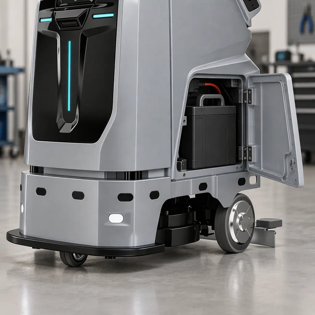
A lithium pack is not a passive box. It carries a battery management system that measures cell voltage, pack current, temperature and state of charge, and it protects the cells against over-charge, over-discharge and thermal runaway. Every one of those measurements is only useful if the BMS can hand it to something else: the robot's controller, the charge dock, or the fleet management software. When the link is missing, the pack still works, but the fleet is blind.
The consequence shows up operationally. A blind fleet cannot rotate packs by state of charge, cannot pre-emptively pull a hot pack, and cannot tell the difference between a pack that is 40 percent full and a pack that is reporting a stale value. The result is the failure mode operators remember: robots dying mid-shift, charge docks that refuse to handshake, and battery faults that are discovered by a customer rather than by a dashboard. Buying a pack without specifying its communication layer is the root cause of most of it.
The protocol is the contract between the pack and everything else. Three protocols dominate service robot battery packs in 2026: RS485 over a simple serial pair, CAN bus as the automotive-derived fieldbus, and Modbus RTU/TCP as the industrial integration layer. Each has a different role, and the right specification usually names more than one.
RS485: The Default for Packs and Docks
RS485 is the most common communication interface on service robot battery packs, and the GSC data on this site confirms the demand: buyers search for packs with RS485 explicitly, because that is the interface their charging dock and controller expect. RS485 is a differential serial bus, which means it survives the electrical noise of a motor-driven chassis far better than a single-ended UART, and it supports multiple devices on one pair of wires, so a pack, a dock and a charger can share a bus.
What RS485 does not define is the message format. RS485 is the physical layer only; the meaning of the bytes on top of it is set by the manufacturer. This is where most integration failures originate: two devices both "support RS485" and still cannot talk, because one expects Modbus RTU frames and the other a proprietary ASCII protocol. The specification must therefore name the protocol on top of RS485, not just the electrical interface.
| Layer | What it defines | What to demand in the spec |
|---|---|---|
| Physical | Voltage levels, wiring, termination | RS485 half-duplex, 120 ohm termination, isolated transceiver |
| Data link | Framing, baud rate, addressing | Explicit baud rate (9600 or 19200 typical) and device address scheme |
| Application | Register/command meaning | A published register map, not a proprietary closed protocol |
The isolation point in that table is not a detail. A pack and a charger sit on a chassis with large inductive loads, and an unisolated RS485 transceiver is a common source of intermittent communication loss that technicians chase for weeks. An isolated transceiver costs a few dollars and removes the whole class of fault.
CAN Bus: The Controller-Side Standard
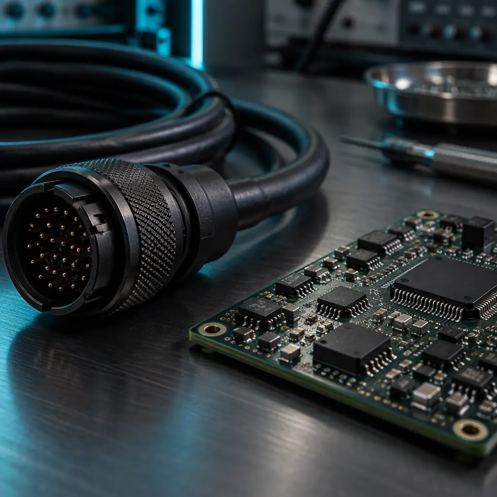
CAN bus is the fieldbus that automotive and mobile machinery standardised on, and it is the natural choice when the battery, the motor controllers, the charge dock and the robot's main computer all need to share one deterministic network. CAN is multi-master, message-prioritised and short-frame, which suits the tight timing of a moving robot: a charge-dock request or a low-voltage alarm is a short, high-priority message that must not queue behind video traffic.
The complication on a service robot is that CAN rarely stands alone. A mixed fleet typically runs CAN on the chassis for motion and battery, and RS485 or Modbus on the ancillary side, then bridges the two in the robot controller or a gateway. The interoperability question is therefore not "CAN or RS485" but "how are the buses bridged, and who owns the translation layer". A vendor that answers only the first question has not specified the integration.
There is also a higher-layer question on CAN. Raw CAN frames carry an identifier and up to eight data bytes, and the meaning of those bytes is again set above the physical layer. In the wider mobile-machinery world this is increasingly standardised through layers like CANopen and J1939, and in multi-vendor fleets through the VDA5050 style of message standard treated in the multi-vendor interoperability guide. For a battery pack, the pragmatic demand is the same as for RS485: a published frame or object dictionary that another engineer can read.
Modbus and the Fleet Integration Layer
Modbus is where the battery stops being a component and becomes a data source for the building. Modbus TCP, running over the same Ethernet as the rest of the building systems, is the protocol a facilities team already knows, and it is the easiest way to surface battery state into a BMS or a CMMS. When a pack exposes Modbus registers for state of charge, temperature and fault code, the building dashboard can show fleet battery health without the operator opening the robot vendor's own portal.
This matters because battery data belongs in the same place as the rest of the operational data. A maintenance system that already schedules the preventive maintenance intervals can add "replace packs below 80 percent state of health" as a trigger if the state of health is readable. A building integration that already pulls occupancy and cleaning data through the sensor layer covered in the occupancy sensor and BMS integration guide can add the charge-dock utilisation in the same pull. The value of Modbus is not elegance; it is that the data lands where decisions already get made.
| Protocol | Best used for | Typical integration cost |
|---|---|---|
| RS485 + Modbus RTU | Pack to dock, pack to controller on the same chassis | Low, if the register map is published |
| CAN bus | Chassis-wide motion and battery network | Medium, gateway needed for other buses |
| Modbus TCP | Battery state into BMS / CMMS / building dashboard | Low, standard for facility teams |
| Proprietary serial | Vendor-internal only | High, locks integration to the vendor |
The Register Map a Buyer Should Demand
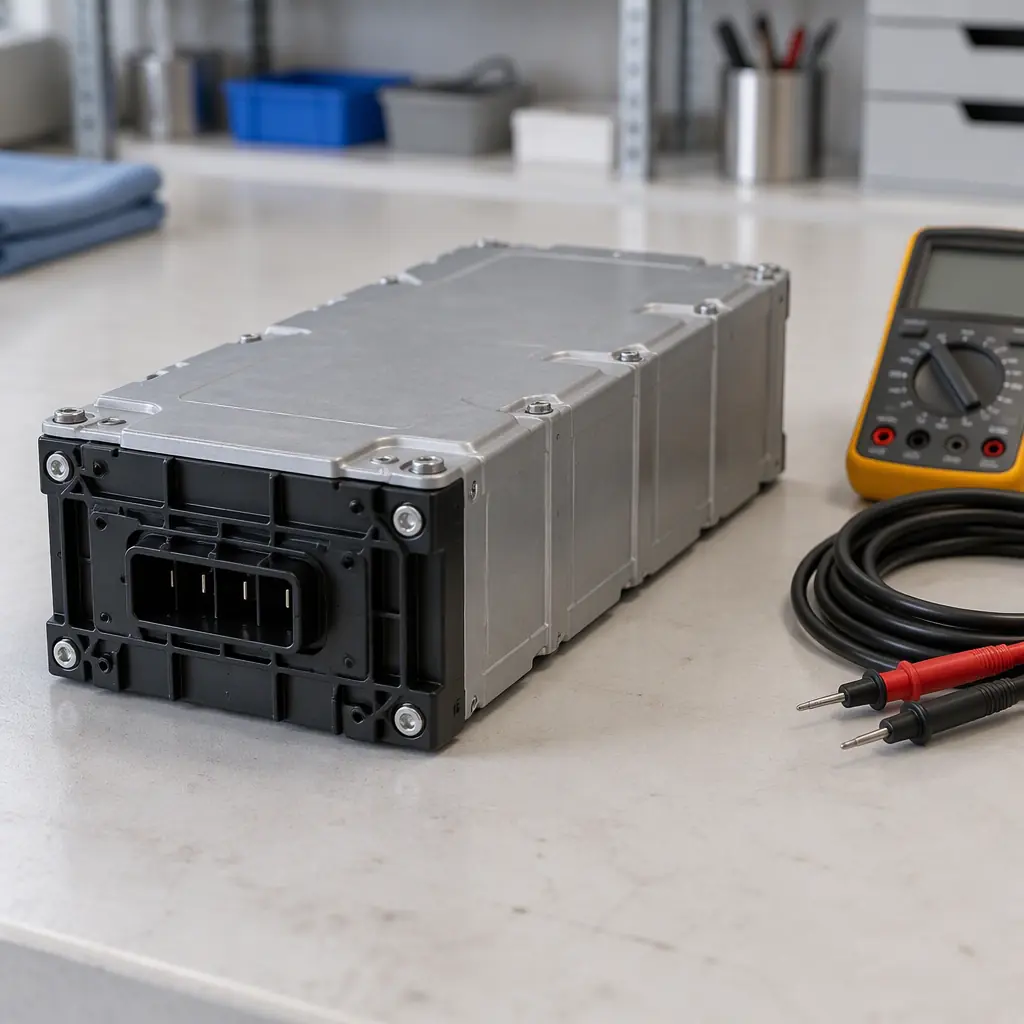
The single most useful line in a battery specification is not the cell chemistry or the capacity in amp-hours. It is the commitment to publish the register map. A published map turns the pack from a black box into a manageable asset, and its absence is a lock-in that will be expensive at the second site. The map should expose, at minimum, seven values.
- State of charge, as a percentage, readable by the fleet software, not only on the vendor's portal.
- State of health, the degradation figure that drives replacement scheduling.
- Pack voltage and current, so the controller can validate the reading against its own sensors.
- Cell temperature and pack temperature, the leading indicator of a thermal fault.
- Fault codes and protection flags, with a documented meaning for each code.
- Cycle count, so the operator knows where the pack sits against its rated life.
- Charge-dock handshake status, so a failed dock contact is visible before a shift, not during one.
When the map is published, the buyer can write the integration contract against it, and the fleet software can do the state-of-charge rotation that keeps a fleet balanced. When it is not published, the buyer is dependent on the vendor for every integration, which is the commercial cost the specification was meant to avoid. As a cross-check on the pack itself, the cell-level choices behind state of health are set out in the battery pack specification and sourcing guide, and the chemistry trade-offs, including the NMC packs common where energy density matters, in the battery charging technology guide.
Charge-Dock Handshaking and Fleet Faults
Most fleet-level charging faults are communication faults in disguise. The dock makes physical contact, but the handshake fails, so the robot reports "not charging" even though the voltage is present. Four checks prevent the whole class.
First, confirm the dock and the pack speak the same protocol on the same bus, not merely the same electrical interface. Second, verify the handshake timeout is long enough for the robot to settle on the dock before the dock declares a fault, because a too-short timeout produces phantom failures at every parking. Third, log the handshake sequence so a failed charge can be diagnosed from the log rather than by a technician at the dock. Fourth, test the bus under load, with the motors running, because a transceiver that works on the bench can fail in the electrical noise of a moving chassis.
The battery lifecycle these checks sit inside is the same one that ends in the battery certification and transport requirements when a pack leaves the site, and the same one the five-year cost model in the total cost of ownership ledger prices as a consumable. Getting the communication layer right at specification time is what makes every later stage of that lifecycle manageable.
Specifying the Communication Layer Correctly
The specification is where the integration is won or lost. Four clauses cover it. Name the physical interface and the protocol stack separately, so RS485 plus Modbus RTU is stated as one line and not conflated. Demand a published register or frame map, with a clear commitment to notify on change. Require an isolated transceiver on any bus that shares a chassis with motor loads. And require the vendor to state how the battery bus bridges to the robot controller and to any building system, not merely that both ends "support the protocol". A pack that passes all four clauses will integrate on the first site and on the tenth, which is the difference between a fleet that scales and one that stalls at the second building.

Get a Quote
Tell us about your space and workload, we reply within 24 hours.