
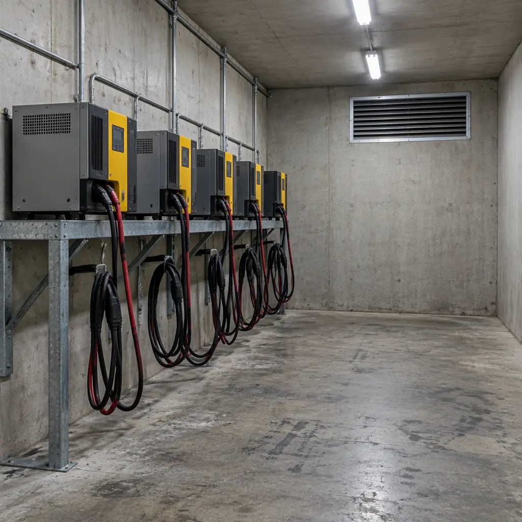
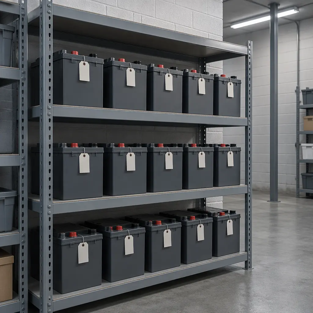
If a fleet still runs on lead-acid packs, the charging room is a hydrogen installation and should be treated as one. The ventilation requirement is not a matter of judgement or of following the battery supplier's leaflet. It is an arithmetic exercise with a defined input — the gassing current during overcharge — and a defined output — cubic metres of air per hour. Most rooms fail the arithmetic not because the fan is too small but because nobody ever did the calculation, and the fan was sized from a rule of thumb that assumed a much smaller bank.
This guide does the calculation end to end for a commercial service robot fleet, covers where the sensor goes and why the obvious position is wrong, and gives the trigger for the decision that most fleet operators eventually face: rebuild the room, or replace the bank with lithium iron phosphate and retire the problem. For the fire side of the same room, see battery fire safety in the charging room; for thermal failure mechanisms in lithium packs, see thermal runaway risk.
Where the Hydrogen Actually Comes From
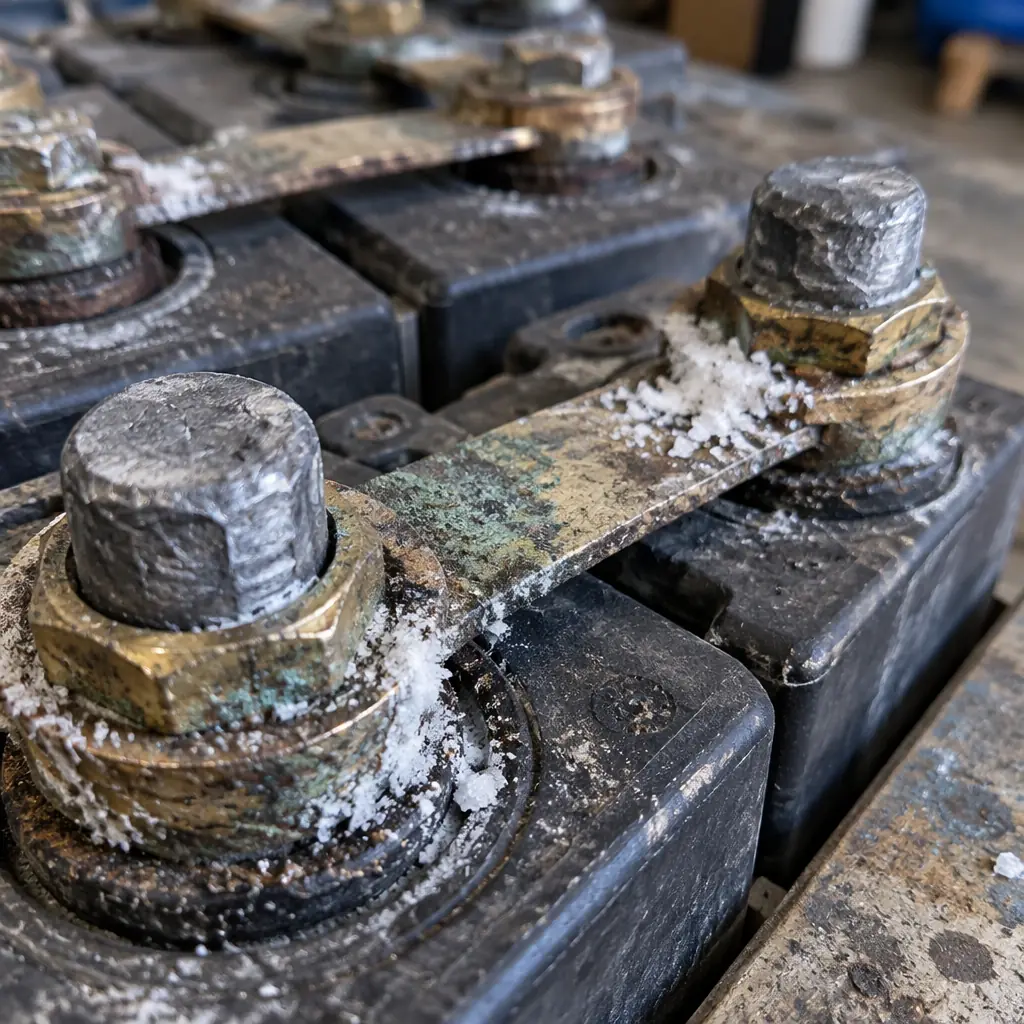
A lead-acid cell produces hydrogen at the negative plate when the charge current exceeds what the cell can absorb. During the bulk phase almost all of it is absorbed in the electrochemical reaction. During absorption and float, the excess current electrolyses water, and the gas output is directly proportional to that excess current. The practical consequence: hydrogen production is not proportional to battery capacity or to charger power, it is proportional to overcharge current, and the worst case is the last hour of a charge cycle on a warm day when the charger is holding a float voltage with every pack still connected.
The gas is also produced at a rate that depends on temperature: a bank at 35 °C gasses materially more than the same bank at 20 °C for the same charge current, which is why charging rooms run warm and why a room that passed its commissioning check in winter can fail the same check in July. No ventilation design should be based on a single measurement taken on one day.
| Charge Phase | Share of Cycle Time | Gassing | Ventilation Demand |
|---|---|---|---|
| Bulk / constant current | 60–75% | Negligible — current is absorbed | Baseline extract only |
| Absorption / constant voltage | 15–25% | Rises through the phase, peak at the end | Full design airflow |
| Float / maintenance | Remainder, and any idle time on the charger | Steady low rate, proportional to float current | Continuous minimum extract |
| Equalise / boost | Scheduled, if used at all | Highest rate of the whole cycle | Forced extract at maximum, interlocked |
The equalise phase is the one that turns a marginal room into a hazard. It is often scheduled monthly and often scheduled automatically at night, when nobody is present and when the extract fan may be on a timer that turns it off. If the room has an automated equalise cycle, the ventilation must be interlocked to it rather than run on a schedule of its own.
The Six-Step Ventilation Calculation
The calculation below follows the structure used by the battery-room ventilation standards and is reproducible with a calculator. Every input is something the fleet operator can obtain from the pack datasheet and the charger.
Step 1 — Establish the gassing current per pack. Take the charger's float or absorption current limit at the end of the cycle, in amperes. For a 24 V 100 Ah pack on a charger with a 10 A limit, the worst-case overcharge current is 10 A, but only the excess above the pack's absorption counts. A conservative working figure is 30–50% of the charge current limit during the absorption phase.
Step 2 — Convert to hydrogen volume. The electrochemical relation gives 0.42 litres of hydrogen per ampere-hour of overcharge per cell at standard conditions. A 12-cell 24 V pack therefore produces about 0.42 × 12 = 5.04 litres of hydrogen per Ah of overcharge. At 4 A of excess current sustained for one hour, that is roughly 20 litres per pack per hour for the worst hour.
Step 3 — Multiply by the fleet. Twelve packs on charge simultaneously gives 242 litres per hour, or 0.24 m³/h. This is a small number, and that is the first surprise: hydrogen volume is not the problem. Concentration is.
Step 4 — Apply the concentration limit. The design limit is 1% hydrogen by volume for continuous conditions, with 2% as the alarm threshold and 4% as the lower explosive limit. Working to 1% means the required air volume is 100 times the hydrogen volume: 0.24 m³/h of gas needs 24 m³/h of air movement. That is a small extract fan, and a room with a 40 W extract running continuously will normally exceed it.
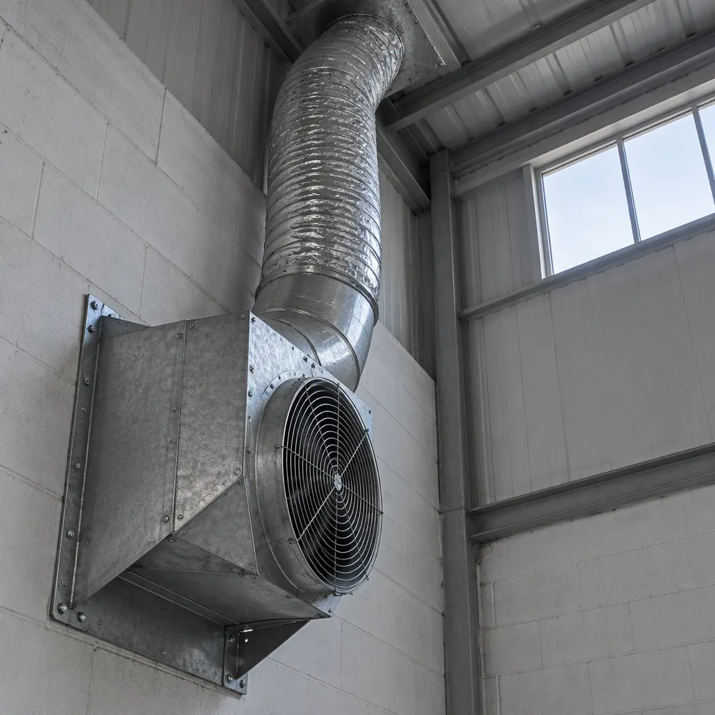
Step 5 — Convert to air changes per hour. Divide 24 m³/h by the room volume. A 3 × 4 × 2.6 m charging room is 31.2 m³, so the requirement is 0.8 air changes per hour. Standards commonly impose a floor of 4–5 air changes per hour for battery rooms irrespective of the gas calculation, and that floor governs: 31.2 m³ × 5 = 156 m³/h, which is a 160 m³/h extract fan.
Step 6 — Check the make-up air. An extract fan is only half a system. If the room is sealed, the extract cannot move its rated volume and the actual air change rate falls well below the design figure. The door undercut or the transfer grille must be sized for the extract flow, not for the door.
| Step | Formula | Worked Example | Common Error |
|---|---|---|---|
| Gassing current | 30–50% of absorption current limit | 4 A per pack | Using the bulk current instead, overstating by 3–4× |
| H₂ volume | 0.42 L × cells × excess Ah | 0.42 × 12 × 4 = 20 L/h per pack | Forgetting the cell count multiplier |
| Fleet total | × number of packs on charge at once | × 12 = 242 L/h = 0.24 m³/h | Counting the whole fleet when only half charges at once |
| Air volume at 1% | H₂ volume × 100 | 24 m³/h | Applying 4% (LEL) instead of 1% |
| Air changes per hour | Air volume ÷ room volume | 24 ÷ 31.2 = 0.8 ACH | Ignoring the 4–5 ACH standard floor |
| Governed design | Greater of calculation and standard floor | 5 ACH = 156 m³/h | Sizing to the calculation and passing an inspection the standard rejects |
The practical takeaway is that on a robot fleet of a dozen packs, the gas calculation almost never governs. The standard's minimum air-change floor governs, and it usually does so by a factor of five. Rooms fail for that reason: the designer did the gas arithmetic, got a tiny number, installed a small fan, and the inspector applied the floor.
Where the Sensor Goes, and Why Not the Ceiling
The intuitive placement is high on the wall or in the ceiling, because hydrogen is the lightest gas and rises. That instinct is correct about the physics and wrong about the design, for two reasons. First, the gas is generated at the battery terminals, and it forms a plume that rises but also disperses; measurement at the point of generation, or in the extract path from it, detects the condition earlier than a ceiling sensor in the far corner. Second, and more importantly, a ceiling sensor behind a light fitting or above a cable tray reads clean air while the breathing zone and the extract grille read the actual concentration.
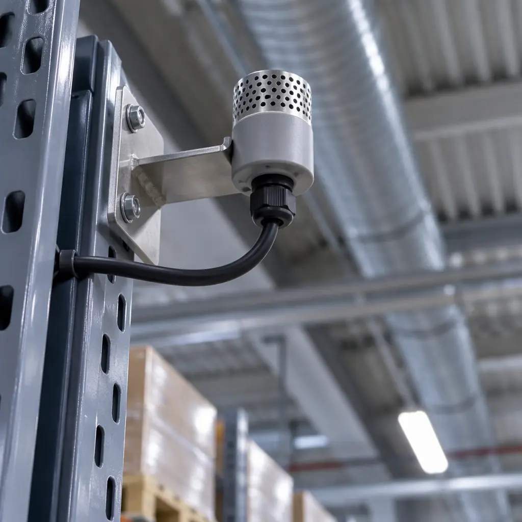
The defensible arrangement is a sensor above each charging bay at roughly 150–300 mm above the top of the tallest pack, plus one in the extract duct if the extract is mechanical. Sensors should be at the high point of the local plume rather than the high point of the room. Two sensors also give a rate-of-rise signal that a single sensor cannot: a concentration climbing between bay and duct means the sensor in the bay is reading a real generation event, while both rising together points at a general room condition.
| Position | Detects | Misses | Verdict |
|---|---|---|---|
| Ceiling centre | Only a genuine room-wide accumulation | A single pack gassing heavily under a shelf; anything masked by ducting | Common and inadequate on its own |
| Above each bay, 150–300 mm over pack top | Per-pack generation at the plume | Duct or plant faults | Required — one per bay on banks above four packs |
| Extract duct | Whether the extract is actually removing gas | Local pockets the extract does not reach | Required where extract is mechanical |
| Floor level | Nothing relevant for hydrogen | Everything | Wrong gas — this is a placement for heavier-than-air vapours |
Alarm thresholds should be set at 10% and 20% of the lower explosive limit, i.e. approximately 0.4% and 0.8% by volume, which sits below the 1% continuous design limit and gives the interlock time to act. The first threshold should force the extract to maximum and raise a local alarm; the second should interrupt charging. A sensor that only alarms is a monitoring device, not a safety function. The fire-safety interlock arrangement that sits alongside it is covered in charging room fire safety.
The Measured Trigger for Retiring the Lead-Acid Bank
The decision to replace a lead-acid bank with lithium iron phosphate is usually framed as a cost question. It is more usefully framed as a room question, because the economics of the swap depend on what the room costs to make compliant. A room that needs a new extract system, an interlock, per-bay gas detection and a fire separation assessment is a capital project. A room that already has all of that is not.
Four measurements decide it, and all four are obtainable within a month of normal operation rather than through a study.
Air changes actually achieved. Measure it rather than trusting the design: door closed, extract running, measure the decay of a tracer or the extract velocity at the grille and multiply. If the room is achieving less than 4 ACH, the room is non-compliant today and the investment is already committed.
Packs failing to reach full capacity. If more than a fifth of the bank shows capacity fade beyond the fleet's replacement threshold, replacement is coming anyway. A lead-acid bank that is being replaced in eighteen months should not have a room built around it.
Cycle count and depth. A lead-acid pack cycled daily to 60% depth returns materially fewer cycles than a LiFePO4 pack in the same duty. The battery chemistry and duty cycle guide sets out the comparison in cycles per euro, and the crossover for an opportunity-charged cleaning platform usually lands inside four years.
Charging window fit. Lead-acid needs a full absorption phase and dislikes partial charging. If the site's operating pattern means packs are returning at 40% and leaving again in two hours, lead-acid will underperform and the charger load profile will be worse than a lithium fleet's. The charging infrastructure and power planning guide covers the electrical side of that comparison.
What to Do This Month
Three actions that cost little and close most of the exposure. Measure the achieved air change rate in the charging room, with the door closed and the extract running, and record it — if it is under 4 ACH the room needs work regardless of the gas calculation. Move or add one hydrogen sensor to the plume above the highest bay, and check the alarm threshold is set at a percentage of the LEL rather than at an absolute ppm borrowed from a different gas. And confirm the equalise cycle, if the chargers have one, is interlocked to the extract rather than running on its own timer.
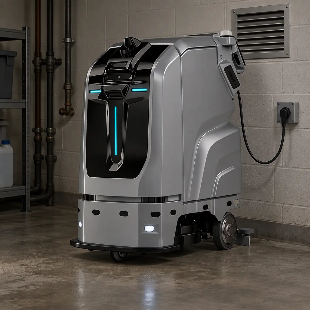
AOMAN FUTURE supplies LiFePO4 packs across the C1, C2 Pro and D1 platforms, which removes the gassing load from the room rather than mitigating it, and the battery and charging technology overview covers the charging profiles those packs expect. If you are deciding between retrofitting a lead-acid charging room and moving the fleet to lithium, send the room dimensions, the pack count and the charger models and we will return the air-change requirement and the swap economics side by side. The same arithmetic is worth running alongside swap station design if the fleet is considering exchange rather than dock charging.