
At a glance: "End of line" means something different in manufacturing than it does in service robotics, and the ambiguity is costing buyers real money. This guide defines the three distinct end-of-line functions on a production line, shows how a service robot is being adapted to each, gives a duty-cycle table for choosing between them, and sets out the cost-per-transfer arithmetic that tells you whether the case closes.
Search for "end of line robots" and you will get a mixed page of results: heavy six-axis arms palletising cartons at the end of a packaging line, and a handful of pages about autonomous mobile robots. Both are correct answers to the query and neither is the whole picture, because "end of line" is a systems term, not a robot category. On a production line it names a location in the material flow — the point where a finished or semi-finished unit leaves the process and becomes a discrete item to be handled, inspected, labelled, tested or moved. Four different functions live at that point, and each one has a different automation answer.
This guide separates those functions, identifies which are properly solved by mobile service robots rather than fixed industrial arms, and gives the duty-cycle arithmetic that decides the choice. The distinction matters commercially because the two categories carry very different capital costs, installation requirements and payback profiles, and a buyer who treats them as interchangeable will specify the wrong machine.
What "End of Line" Actually Names
In industrial engineering the end of line is the boundary between in-process handling and outbound logistics. Work that happens at that boundary falls into four functions, and they are worth naming separately because they are frequently bundled into one procurement brief with one budget line.
| Function | What Happens | Cycle Character | Standard Automation |
|---|---|---|---|
| Transfer and sortation | Finished units move from the line output to a buffer, cart or conveyor that feeds outbound | Continuous, short cycle, high repetition | Fixed conveyor, gantry or cobot arm |
| Inspection and test | Functional test, vision check, leak test, print verification, dimensional check | Cycle time equal to line takt; station-bound | Fixed test cell with part-present sensor and reject gate |
| Label, mark, trace | Serialisation, label application, laser marking, vision-verified identity | Fast, in-line, regulatory-driven | Fixed printer-applicator or marking head on the line |
| Inter-line and warehouse transfer | Batches move between line ends, to staging, WIP buffer, QA hold or finished-goods area | Batch, variable route, long distance | Manual tug and hand cart, or AMR / AGV |
The first three functions are line-bound and happen at a fixed geometry, which is why they are the traditional domain of fixed automation: the part arrives at a known place at a known time, so a fixed arm or gantry is the cheapest way to act on it. The fourth is not line-bound at all. It is a transport problem along a route that changes with the production schedule, and that is the function where mobile robots are being deployed and where the economics are most often misjudged.
Where Mobile Robots Fit — and Where They Do Not
The practical question is not whether a mobile robot can reach the end of a line. It is whether the task at that line end has the characteristics that make mobility pay. Mobility is worth its cost when the route varies, the distance is substantial, the payload is within the platform's envelope, and the surrounding infrastructure cannot easily be rebuilt. It is not worth its cost when the geometry is fixed and the cycle is short, because a fixed device with no navigation stack, no battery and no fleet software will always be cheaper for the same throughput.
The clearest cases in current production environments are the ones where a line end generates discrete batches that must travel. Tooling and fixture returns from a machining cell to a tool crib. Printed circuit assemblies moving from an SMT line end to a conformal-coat or test area across a bay. Sub-assemblies travelling from a line end to a burn-in or soak rack. Finished units from a line end to a kitting or packing area that is deliberately kept out of the production hall for cleanliness reasons. Each of these has a route that varies by product and a distance that a person currently walks or drives, which is exactly the profile where a mobile platform carries its own weight.
| Task Profile | Distance | Route Variability | Preferred Answer |
|---|---|---|---|
| Line-end transfer to adjacent buffer, under 5 m | Short, fixed | None | Fixed conveyor or end-of-line arm |
| Line end to test cell within same bay, 5–20 m | Medium, fixed | Low | Powered roller conveyor or cobot, occasionally AMR |
| Line end to WIP buffer across the hall, 30–150 m | Long, semi-fixed | Medium | Mobile robot, high case quality |
| Line ends of multiple products to one staging area | Long, multi-origin | High | Mobile robot, fleet-managed — strongest case |
| Line end to off-site or inter-building transfer | Very long | High | Mobile robot with weatherproof platform, or dedicated route |
Read the top two rows as a warning. A meaningful share of proposed end-of-line robot projects are actually short fixed-distance transfers that a conveyor or a simple powered roller would do for a fraction of the cost, and the mobile platform is proposed because it requires no civil work. That is a real advantage, but it is a capital-avoidance advantage, not a labour-saving one, and it should be justified on that basis rather than on a labour comparison that will not materialise.
The Duty Cycle Arithmetic
Whether a mobile platform is the right answer at a given line end comes down to whether there is enough transport work to occupy it. That is a throughput calculation with five inputs, and it can be done before any vendor is contacted.
| Input | How to Measure It | Worked Example |
|---|---|---|
| Batch rate | Batches per shift generated at the line end | 18 batches per shift |
| Route distance, one way | Metres from line end to destination, measured not estimated | 110 m |
| Platform speed under load | Design speed × 0.7 for acceleration, doorways and traffic | 1.2 m/s × 0.7 = 0.84 m/s effective |
| Handling time per transfer | Load, secure, release, confirm — observed over 20 cycles | 70 s per end, so 140 s per round trip |
| Shift length available | Productive hours, excluding charging and breaks | 6.5 h of an 8 h shift |
From those, a round trip takes 2 × 110 m ÷ 0.84 m/s = 262 s of travel, plus 140 s of handling, or 402 s total — about 6.7 minutes. Eighteen batches per shift is a demand of 18 × 6.7 = 121 minutes, roughly 2 hours of a 6.5-hour productive window. The platform is therefore utilised at about 31 percent on this task alone. That number is the decision input, and it cuts both ways: a single robot is comfortably sufficient, which means buying a fleet is waste; but the same number says the platform is idle for two thirds of the shift, so a business case built on displacing a full-time person will not survive scrutiny unless additional routes are assigned to it.
The utilisation figure is also where these projects succeed or fail in practice. A robot at 30 percent utilisation on one route is not a bad investment if it takes over two or three more routes in the same building. It is a poor one if it does not, and the difference is a route-planning question rather than a hardware question. The consolidated version of this arithmetic, including the second and third routes, is what should appear in the business case. The measurement framework for the rest of the fleet is in service robot KPI benchmarks.
Interfaces: Where End-of-Line Projects Actually Stall
The hardware decision is usually the easy part. What stalls end-of-line robot projects is the interface between the robot and everything already there, and the three interfaces that cause the most delay are worth planning around specifically.
The first is the physical interface at the line output. A mobile robot does not accept a carton from a conveyor; something has to place the load, or the load has to arrive on a carrier the robot is designed to move. Retrofitting a line end with a transfer station is a civil and mechanical project with its own lead time, and it is frequently the longest item on the critical path. The second is the transactional interface: the robot needs to know which batch is which and where it is going, which means either a handheld scan step by an operator or an integration between the fleet software and the MES or line controller. A scan step is cheap and adds a few seconds per transfer; MES integration is expensive, slow and often the element that turns a three-month project into a twelve-month one. The third is the safety interface, because an AMR operating in a production hall has to be assessed against the machinery safety regime of the line it serves, not treated as standalone equipment.
The practical consequence is a sequencing rule. Pilot the transport route in a low-complexity area first — a WIP buffer run with a manual scan step — to prove the navigation and the handling, and only then integrate with MES. Projects that begin with the integration attempt to solve the hardest problem before proving the easiest, and they are the ones that get cancelled in month four. The manufacturing-site context for that pilot is covered in service robots in manufacturing and industrial automation.
Cost Per Transfer: The Comparison That Decides It
The comparison that survives a finance review is cost per transfer, normalised across the options. The manual baseline is the easiest to compute and the one most often overstated by vendors. A material handler on a two-shift operation costs the fully loaded rate — wage, benefits, supervision, absence cover — which in a European or North American manufacturing environment lands in a range that is not small, but the false step is attributing the whole cost to the transport task when transport is typically only part of that person's shift.
| Option | Annualised Cost Basis | Cost Driver | Scales With Volumes? |
|---|---|---|---|
| Manual material handler | Fully loaded labour rate × FTE share devoted to transport | Labour, absence, turnover, rework from handling damage | Yes, linearly — volume growth needs more people |
| Fixed conveyor or gantry | Capital, installation civil work, controls, maintenance | Change costs: any line change requires mechanical rework | No — but changeover is expensive and inflexible |
| Tug and cart fleet | Low capital, high labour, low flexibility | Route fixed to driver availability; no data output | Yes, and poorly — driver count grows with routes |
| Mobile robot platform | Capital amortised plus service contract plus charging power | Route count, not batch count; utilisation decides payback | Sub-linearly — spare capacity on existing routes absorbs it |
The decisive column is the last one. Manual transport gets more expensive in direct proportion to production volume, and fixed automation gets more expensive every time the line changes. A mobile platform scales sub-linearly, because the marginal batch on an existing route costs almost nothing once the machine is amortised. That is the structural argument for the category, and it is a better argument than the labour-replacement pitch, because it holds even when a full-time equivalent is not actually removed. The wider recurring-cost picture — service, consumables, power — is set out in maintenance and total cost of ownership.
What to Ask Before You Specify
Six questions, each designed to surface a project risk before it becomes a cost overrun.
- What is the measured route distance and round-trip time? Not the straight-line distance on a floor plan. Measured, at production speed, with doorways and traffic.
- What places the load onto the platform? If the answer is a person, the business case has a labour component that will not go to zero, and that should be priced in rather than discovered at commissioning.
- Is the identification step manual or integrated? A scan step is acceptable and cheap. An MES integration needs its own budget, owner and timeline, separate from the robot project.
- Does the platform handle the payload envelope, including imbalance? Rated payload and usable payload differ once the load is asymmetric or the centre of gravity moves.
- What is the intended utilisation, and which routes make up the rest of it? A single-route duty cycle rarely justifies the platform. Ask for the multi-route plan at the same time as the quote.
- How does the machine behave when the network is down? A transport robot that stops when the dispatch service is unavailable is an availability risk in the middle of a production shift, and that risk belongs in the assessment.
Those six answers, plus the duty-cycle table, convert an end-of-line robot proposal from a vendor narrative into a costed engineering decision. That is the standard the category deserves, because the technology is genuinely capable and the failures in this space are almost always specification failures rather than hardware failures. For the analytical layer that should sit alongside a mobile transport deployment — predictive maintenance from fleet telemetry — see what telemetry actually predicts; for the safety assessment path an AMR in a production hall requires, see safety and compliance standards.
How AOMAN Fits an End-of-Line Environment
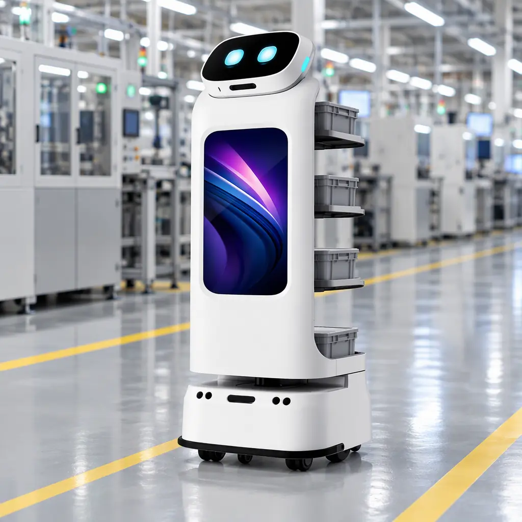
AOMAN FUTURE builds service robots for delivery, cleaning and guidance, and the platform most relevant to production environments is the D1 delivery robot — a compact autonomous carrier with three open tray shelves on a side column, a white body with a front display screen, and a power base with a black sensor band. On a factory floor it moves assemblies, fixtures, small tooling batches and QA samples between line ends, WIP buffers and staging areas, with fleet navigation and task assignment managed from the AOMAN dispatch platform.
The honest boundaries are worth stating plainly, because they decide fit. The D1 is not a palletising machine and it is not a vision inspection cell; it does not lift cartons off a conveyor, and it does not replace a fixed end-of-line arm for line-bound work. It moves what fits within its tray envelope, along routes you map, and it is designed to keep operating within its mapped zones if the cloud layer is unavailable, which is the availability property that matters most in a production environment. For facilities combining transport with floor cleaning, the C1 large-format scrubber and C2 Pro compact cleaner run on the same fleet and dispatch layer, so a site can address both duties with one management interface. If your line end generates a batch that currently travels by hand or by tug, send us the route and the batch rate and we will run the duty-cycle arithmetic above against your actual numbers.