
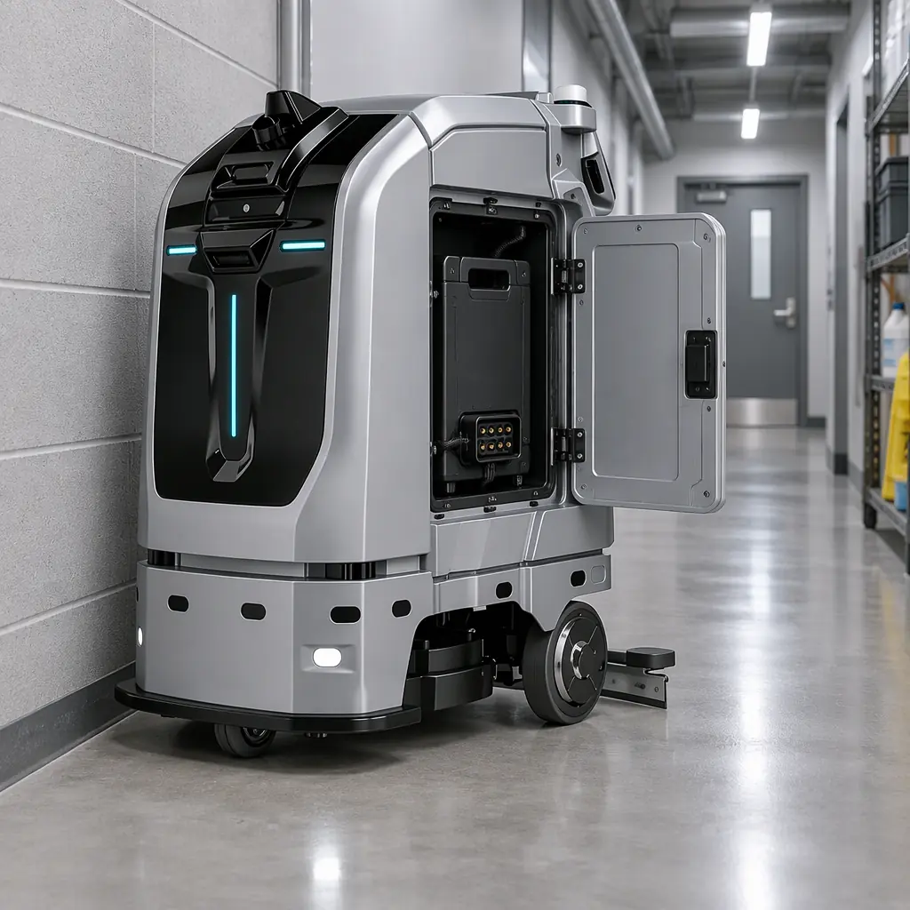
Most RS485 battery-bus failures are not protocol failures. They are electrical ones, and they cluster in a narrow band of decisions made once, at design time, by someone who has usually specified RS485 before on a building sensor network and reasonably assumed a battery pack is the same problem. It is not. A pack bus lives inside a machine that vibrates, swaps packs by hand, sits on a charger whose earth reference is not the machine earth, and carries a connector that gets mated several thousand times. Four decisions determine whether that bus is boring or a recurring service ticket: isolation, common-mode window, termination that is measured rather than assumed, and arbitration timing that survives a full pack population.
This page covers the transceiver layer specifically. For the choice between CAN and RS485 as a link protocol, see CAN bus versus RS485 for battery packs. For what the pack should expose once the link is running, see battery communication protocols. For the register-level spec to send a supplier, the RS485 battery specification guide covers the document itself.
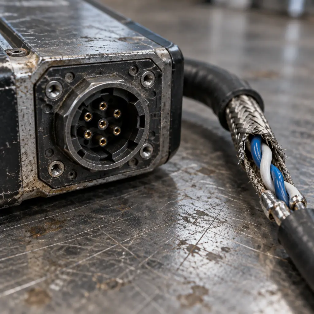
Why the Same Transceiver Fails Inside a Robot and Not on a Wall
An RS485 link on a building network connects two devices that share a panel, a mains feed and an earth. A robot pack bus connects a device that is being charged from a docking plate, to a host controller that is referenced to the chassis, on a machine whose wheels may be sitting on a floor at a different potential from the charger's earth, through a connector that a human just pushed in with their body in the loop. Three of the four error sources that matter on a robot bus simply do not exist on a wall-mounted link.
| Error Source | Wall Network | Robot Pack Bus | Consequence If Ignored |
|---|---|---|---|
| Ground potential difference | Millivolts, shared earth | Volts, separate earths at dock, and different again when the charger is on a different circuit | Common-mode excursion beyond the transceiver window, garbled frames, or a destroyed driver |
| Surge during pack insertion | Absent | Hot-mate: contact pins connect power and data in an order set by mechanical tolerance, not by design | Transient into the receiver during insertion, locking the bus until power cycle |
| Cable length | Metres to a kilometre, engineered | 0.4 to 2 m, bundled with motor phase cables | Short cable, so people skip termination, then fight reflections from stubs |
| EMI | Low | Brush motors, vacuum motors and a 48 V switching converter on the same harness | Bit errors that appear only under load, never on the bench |
The pattern in the last row is the diagnostic trap. A pack bus that passes a bench test and fails on a working machine is telling you the problem is coupling, not the protocol stack, and no amount of retry logic fixes a physical-layer margin problem.
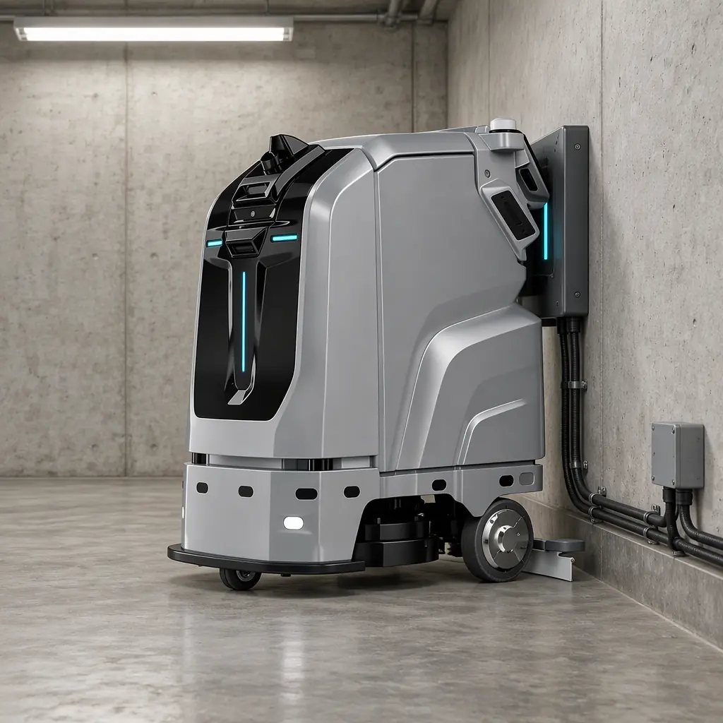
Isolation Is Not Optional, and the Number That Matters
An isolated transceiver separates the bus-side referenced circuit from the pack-side logic, so a ground potential difference appears across the isolation barrier instead of across the receiver inputs. Every pack that sits on a charger with a separate earth should be isolated, and the specification to care about is not the isolation technology but the working voltage and the transient rating.
For a 48 V robot pack bus the working isolation voltage requirement is modest, but the transient requirement is not, because the pack-side circuit is directly exposed to the battery and to insertion transients. A transceiver rated for 2.5 kVrms basic isolation with reinforced creepage across the connector gap is the sensible floor. Below that you are relying on the connector's mechanical sequencing to keep the grounds apart long enough, which is a tolerance, not a guarantee.
The second isolated component that gets forgotten is the transceiver's power rail. An isolated transceiver needs an isolated supply on the bus side, and a cheap isolated DC-DC with poor transient response will collapse during pack insertion and reset the transceiver mid-frame. If a fleet reports intermittent "pack not found" that clears after a dock cycle, this is the first thing to scope.
| Parameter | Value to Specify | What It Protects Against | How to Verify at Goods-In |
|---|---|---|---|
| Isolation working voltage | ≥ 2.5 kVrms, 1 min, bus side to logic side | Ground potential difference between chassis and charger | Hipot test on a sample, not per unit — ask for the type-test report |
| Isolation transient rating | ≥ 6 kV peak, 10/700 µs waveform | Insertion surge, ESD through the connector shell | Type-test report plus the connector's own ESD rating |
| Isolated rail transient response | Holds regulation within ±5% for a 100 mA load step in < 200 µs | Transceiver reset mid-frame on pack insertion | Scope the rail during a real insertion, not a bench load step |
| Isolation barrier on the data pair | Both A and B lines on the isolated side, no shared return | Common-mode current finding a path through the logic ground | Continuity check: logic ground must not ring to connector ground |
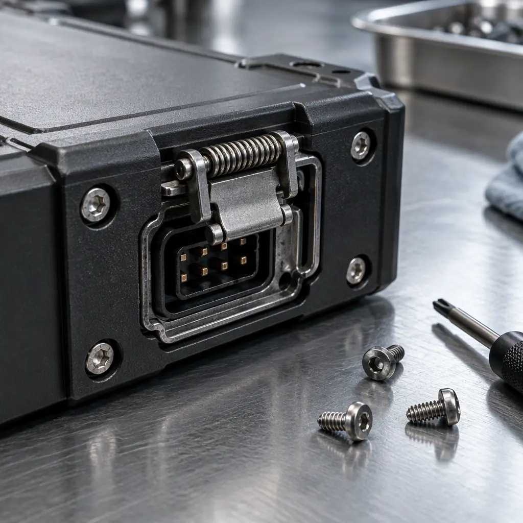
The Common-Mode Window Is Where Fleets Actually Break
The transceiver's differential receiver has a specified common-mode range, typically −7 V to +12 V on a standard part. That number is a hard boundary, and it is the one that gets crossed in the field rather than on the bench. Two conditions push a robot bus outside it.
The first is the dock. When a robot is on a charging plate, the chassis is referenced to the charger, and if that charger is on a different distribution board from the building earth the pack's bus reference can sit several volts off the controller's. The second is a long harness run alongside motor phase cables, where capacitive coupling injects a common-mode swing on both A and B in phase — differential signalling rejects it, but only while the receiver stays inside its input window.
The practical specification is to require a transceiver with an extended common-mode range of −20 V to +25 V rather than the standard −7/+12 V part, and to treat that as a hard selection criterion rather than a nice-to-have. The cost difference at volume is a few cents per pack. The warranty difference is measured in service visits. Where an extended-range part is not available, a galvanic isolator on the bus pair achieves the same effect, which is why isolation and common-mode tolerance are usually specified together even though they solve different problems.
A quick field diagnostic: if a pack reports reliably on the bench and intermittently on the dock, and the error rate correlates with which charger the robot is on, the common-mode window is exceeded on that charger. Earth-bond the charger to the building earth and re-test before replacing any hardware. If the fault follows the charger rather than the robot, it was never a pack problem.
Termination: Measure It, Do Not Assume It
The standard advice — 120 Ω at each end of the bus, nothing in between — is correct and almost universally implemented incorrectly on robot packs, for a mechanical reason: the second terminator lives inside the pack, and the pack is removable. Every pack that comes off the line either has its terminator fitted or it does not, and nobody notices until a bus with three packs on it starts dropping frames.
There are two defensible architectures and one indefensible one. The indefensible one is fixed termination in every pack, which works with one pack and fails with three because the parallel resistance collapses. The two workable options are a bus that terminates only at the host and at the far end of the harness (requiring the packs to be stubs, which limits how many can share the segment), or software-selectable termination in each pack driven by an address pin or a command, which is what most multi-pack designs end up at.
| Architecture | Max Packs per Segment | Termination | Failure Mode if Misconfigured |
|---|---|---|---|
| Host terminator + fixed pack terminators | 2 | 120 Ω at host, 120 Ω in each of two packs | Third pack halves bus resistance to 40 Ω, driver current rises, frames corrupt under load |
| Host terminator + harness end terminator, packs as stubs | 4–6, stub < 0.3 m | 120 Ω at each harness end only | Stub longer than 0.3 m produces reflections that corrupt the first bytes of a frame |
| Selectable termination per pack | 8 with 0.4 m spacing at 19.2 kbps | Only the two physically end-most packs enabled | Two packs both think they are the end: 60 Ω, marginal; no pack enabled: bus floats, no idle bias |
Measure it rather than trusting the design: with the bus powered down and all packs disconnected, measure resistance across A and B. A correctly terminated two-end bus reads 60 Ω. Anything else tells you exactly what is wrong before you spend a shift on protocol traces. This is the single fastest check in this entire article and it takes ninety seconds with the machine's side panel off.
While the meter is out, check the idle bias. A terminated RS485 bus with no driver enabled sits at an undefined differential level unless a bias network pulls A above B. Many transceivers have internal fail-safe bias, but not all, and a bus that works with a powered host and fails during the window when the host is booting is usually a bias problem rather than a timing one.

Arbitration Delay: Why Your Poll Cycle Slips as the Fleet Grows
Modbus RTU over RS485 is half duplex and polled. Only one device talks at a time, and the master has to wait a specified turnaround before assuming a slave is not answering. That turnaround is what makes a pack bus slow to scale, and it is the number nobody puts in the tender document.
The arithmetic is unglamorous and worth doing before specifying. Each transaction costs a request frame, the pack's response, and a turnaround gap. At 19,200 bps with 8 data bits, one stop bit and no parity, ten bits go on the wire per byte, so a 20-byte transaction takes about 10 ms. Add a 20 ms turnaround to be safe against a slow pack and each register read is roughly 50 ms. Ten registers on each of six packs is 3 seconds. Read those registers every five seconds across a 40-robot fleet from one gateway and the gateway is saturated before it starts, which is exactly how "the telemetry drops out at peak" gets reported and blamed on Wi-Fi.
| Baud Rate | Max Packs per Physical Segment | 10-Register Read per Pack | Full Fleet Poll, 6 Packs x 8 Robots |
|---|---|---|---|
| 9,600 | 8 | ~100 ms | ~4.8 s — usable only for hourly snapshots |
| 19,200 | 8 | ~50 ms | ~2.4 s — fine for 60 s reporting, too slow for alarms |
| 57,600 | 6 | ~20 ms | ~1.0 s — the usual choice for fleet telemetry |
| 115,200 | 4 | ~12 ms | ~0.6 s — short harnesses only, and check error rate at temperature |
The three levers that actually work are: read blocks rather than individual registers, so ten values cost one transaction instead of ten; split the bus so each segment has its own master port; and let the pack push exception events rather than waiting to be polled. The third is what makes an alarm latency of under a second possible on a bus that cannot poll fast enough to notice the event on its own.
What to Put in the Pack Specification
Six lines in the datasheet request separate packs that will work from packs that will generate service tickets in year three. Isolation working voltage and transient rating, with the type-test report named as a deliverable. The transceiver common-mode range, stated as a number rather than as "RS485 compliant". Termination architecture, stated as a count of packs supported per segment. Idle bias, stated as present or absent. Baud rates supported with the maximum segment length at each. And the insertion-surge behaviour: what the pack does if the data pins mate before the power pins.
AOMAN's pack interface documentation states these values per model rather than pointing at a generic RS485 claim, because the specification is only useful if it is the actual part. For a pack specification review against your own harness and dock design, send the harness drawing and the charger earthing arrangement and we will return the common-mode and termination assessment with the model datasheet. If you are still deciding whether the bus should be RS485 or CAN at all, the interface comparison and the pack sourcing guide cover the decision above this layer, and the swap station design guide covers what changes when packs are exchanged rather than dock-charged.