
UPS and Power Conditioning for a Robot Fleet
At a glance: A robot fleet does not plug into the wall the way a hand dryer does. Every charging dock is a load that drops out and returns every few dozen minutes, and that pattern punishes a building's electrical infrastructure in ways a steady load never does. This guide works through the four infrastructure costs that sit between the dock and the utility meter: dock circuits, surge protection, the UPS sizing arithmetic, and power conditioning. It also sets out what the fleet controller must do in the seconds after an event, which is the part that decides whether a dip costs an hour of cleaning or nothing at all.
Why a Robot Fleet Is Not a Steady Electrical Load
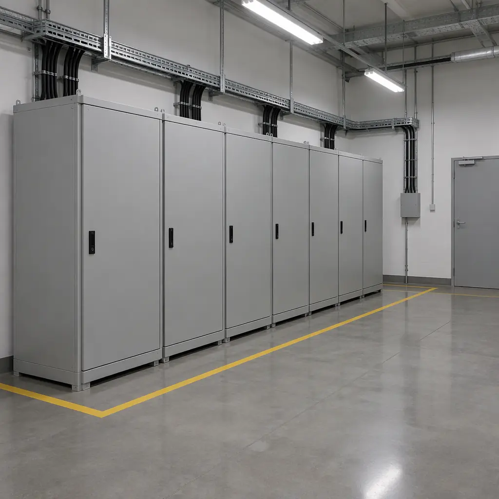
Most of the infrastructure cost of a robot fleet is not the energy it consumes, it is the cost of keeping the dock energised through every event the building throws at it. A dock is a switched load with an awkward profile: it draws between 400 W and 3 kW while a pack charges, drops to a few watts on standby, then comes back an hour later. Multiply that by a fleet in shift rotation and the site ends up with a cluster of loads switching on and off all night, on one circuit, in a room nobody designed for it.
That pattern produces three effects a steady load does not. It produces inrush current at every dock start, which trips breakers sized on continuous current. It produces voltage sag at the far end of a long final circuit, which a charger tolerates and an onboard computer may not. And it means any upstream power quality event, from a storm dip to a transfer between utility feeds, lands on equipment that is either mid-charge or mid-mission.
The commercial translation is simple. A robot that aborts a mission because the dock lost power for four seconds does not resume where it stopped. It returns, re-docks and loses the run. In a night window of fixed length, that lost run is either an incomplete clean or a paid manual re-run, and the infrastructure line exists to make it rare rather than weekly.
The Four Infrastructure Line Items
A fleet quote rarely includes these, because they sit inside the building rather than inside the robot. Each has a defensible cost and a defensible reason, and the reason is what carries a finance conversation.
| Line item | What it protects | Typical scale | Failure mode if omitted |
|---|---|---|---|
| Dedicated final circuit per dock pair | Breaker trips when two docks start at once | One 16 to 32 A circuit per two docks | Half the fleet charges while the other half faults out |
| Dock-side surge and sag protection | Charger control board and robot onboard computer | Per-dock device, DIN rail or outlet type | Charger resets mid-charge; repeated resets shorten charger life |
| UPS for the fleet controller and network | Mission queue, dispatch state, dock telemetry | 1 to 3 kVA behind the dock controllers | A four-second dip wipes the night's dispatch plan and the fleet stops |
| Power conditioning at the panel | Every dock on the circuit group, where quality is chronically poor | Panel-level device, sized on circuit kVA | Chronic dips reach every dock, every night |
Two of the four lines are usually already present in a commercial building and two are usually not. A building has final circuits; it rarely has one sized for a dock cluster. A building may have a UPS on its server room; it does not have one on the robot room. The design task is to work out which two are already paid for, because the answer moves the infrastructure number by a factor of three.
UPS Sizing: The Arithmetic That Survives a Review
UPS sizing for a fleet is not a whole-building calculation. It is a calculation of how much load must ride through, for how long, and what the load's starting current is. The method below produces a number a finance reviewer can check line by line.
- List what must ride through. Not the robots on charge and not the cleaning task. The critical set is the fleet controller, the site network switch, the dock controllers, and any access control that keeps staff out of an unlit charging room. In most fleets that is 300 W to 1.2 kW.
- Set the ride-through time from real outages. Ask facilities for 24 months of power events and their durations. A site with a generator and an automatic transfer switch needs two to four minutes. A site without one needs the time it takes a named person to walk to the room and shut the dock group down cleanly. Write that number down rather than defaulting to ten minutes.
- Size on apparent power and starting load. Sum nameplate watts, convert at a power factor of 0.8 for a mixed controller and network load, then add 25 percent headroom for a cold start where every dock controller powers up together. A 900 W critical set becomes about 1,125 VA, and with headroom roughly 1,400 VA, so the nearest standard size is 1,500 VA.
- Use end-of-life battery capacity, not new capacity. A lead-acid UPS at end of life delivers 60 to 70 percent of rated runtime. If the site genuinely needs four minutes in year five, it needs about six minutes in year one. That is the difference between a unit with internal batteries and one with an external string.
- Check transfer time against the loads. A controller that reboots on a 20 ms transfer defeats the purpose. Either specify double conversion, or specify line-interactive and confirm every critical device rides through the transfer. A vendor who has measured it will answer in writing; one who has not will say it depends.
The result is usually modest, 1 to 3 kVA protecting a load worth less than a month of the fleet's energy. The value is not the load, it is the dispatch state that load holds. A controller that loses its mission queue at 22:40 does not recover by itself, because the person who can rebuild the queue is at home.
Surge Protection, Power Conditioning and the Difference Buyers Miss
Three devices are sold under one name and they solve different problems. Buyers who treat them as interchangeable either overpay for protection they do not need or buy the wrong device and assume the risk is covered.
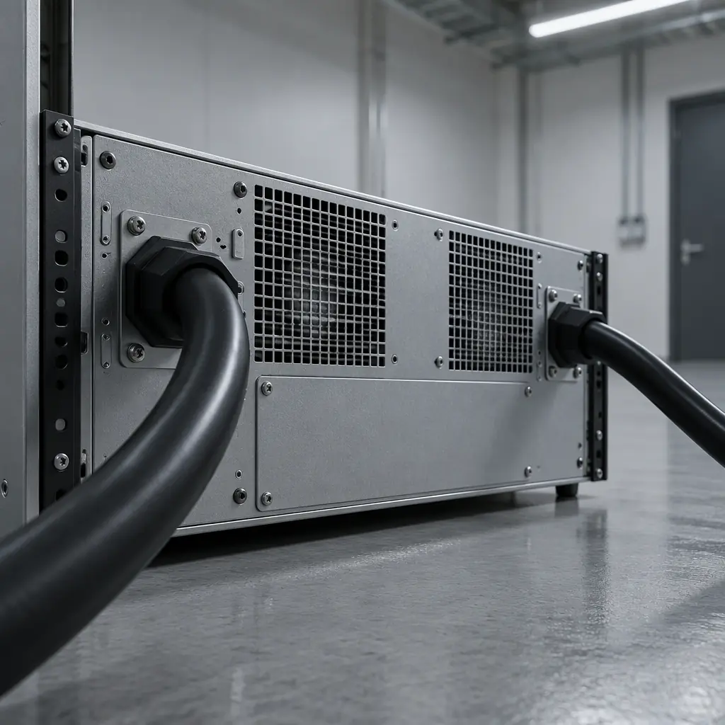
- Surge protective device. Clamps a fast, high-voltage transient, typically a lightning-induced spike or an inductive kick from a large motor switching. It reacts in nanoseconds to a thousand-volt event and does nothing for a sustained dip. Mount one at the panel feeding the dock group and again at the dock if the cable run is long.
- Line-interactive UPS. Holds the load through dips and outages by switching to an inverter, and performs modest voltage regulation through a tap-changing transformer. It does not correct frequency or harmonic distortion.
- Double-conversion UPS or power conditioner. Rectifies incoming power and regenerates a clean sine wave at the output, so dips, harmonics and frequency deviation stop at the input. It is the right device for a site with a chronic quality problem, an ageing supply, or docks sharing a panel with heavy motor loads. It is the wrong device for a site whose only risk is the occasional storm outage.
The diagnostic question that separates the three cases is what facilities can show you. Twenty-four months of event logs with depths and durations makes the decision arithmetic. A site with nothing documented is better served by a surge device at the panel, a line-interactive UPS on the critical set, and a one-month power quality logger on the dock circuit. The logger costs a fraction of a conditioner and turns an opinion into a measurement.
What Charger Behaviour Does to a Weak Supply
The charger interacts with the building more directly than any other part of the fleet, and its tolerance is routinely overestimated. A pack BMS reduces charge current long before it complains, so a weak supply can quietly turn a three-hour charge into five without any alarm. On site that appears as a robot finishing a shift below the state of charge the schedule assumed, and then as a dock queue overrunning the night window.
Two charger behaviours are worth specifying in writing. The first is the minimum input voltage at which the charger still delivers full current; below that it should derate cleanly and report the derate rather than cut out and restart. The second is the restart hysteresis after a dropout, so a dock does not chatter between charging and faulting through a series of short dips. Both are testable at commissioning with a variable transformer and a laptop on the charger's communication port, and an afternoon of testing settles what the datasheet leaves ambiguous. The pack-side consequences of that derating are covered in the battery charging technology guide, and the room-side electrical design in the charging infrastructure and power planning guide.
Costing the Line Without Guessing
A buyer needs a number before a decision, not after a survey. The table below lists each item with its basis, so the quote can be rebuilt with local rates.
| Item | Basis | Eight-dock building |
|---|---|---|
| Dock circuits | Per dock pair, including cable, breaker and isolator | Four circuits at two docks each |
| Panel surge device | Per panel feeding the dock group | One device on the dedicated panel |
| Critical-set UPS | 1 to 3 kVA, runtime to the site's stated figure | 1,500 VA covering controller, switch and dock controllers |
| Power quality logger | One month on one dock circuit | One unit, returned or retained after measurement |
| Commissioning test | Half day of electrician plus integrator | Sag and dropout test on one dock, then the group |
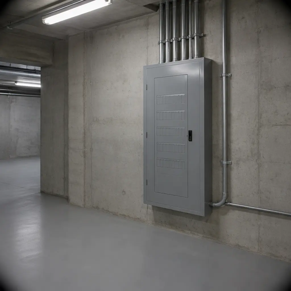
The whole line typically lands at two to five percent of the robot capital on a single-site fleet, and falls as the fleet grows because the UPS, the logger and the panel device do not scale with dock count. Two things push it upward: an old supply that needs conditioning rather than a small UPS, and a dock room with no spare panel capacity, requiring a new sub-board. Both are better found in a survey than during commissioning, which is why the site survey and readiness assessment guide puts the electrical room on the ninety-minute walk.
What the Fleet Controller Must Do When Power Fails
Hardware is half the answer. The other half is software behaviour in the seconds after an event, and this is where fleets differ most. Three behaviours belong in the contract rather than in hope.
- Hold the queue through the ride-through window. When the UPS carries the controller, the queue should persist and resume on its own. The test is not that the controller survives; it is that the 23:00 dispatch is still there at 23:10 with nobody touching anything.
- Park, do not abandon. A robot that loses its dock mid-charge should move to a safe parked position and hold, reporting the reason. A robot left mid-corridor blocks a fire route and becomes somebody's evening problem.
- Reconcile the plan on restart. After a longer outage the controller should recompute the remaining window against remaining battery and tell the operator which zones will not be cleaned. The failure to avoid is the silent one, where the plan resumes as if nothing happened and the shortfall appears in the morning inspection.
All three are cheap to specify and expensive to retrofit, because they live in firmware and the fleet layer rather than in a spare part. They belong in the same conversation as the availability clauses in the service credits and availability clauses guide, and they change what the UPS is protecting: not the hardware, but the commitment the operator made to the client.
Commissioning Test: Prove It in an Afternoon
The infrastructure line is only as good as the test that follows it. Four checks cover the failure modes that actually appear in the first year.
- Concurrent start. Bring every dock up at once from cold with the robot fleet attached and confirm no breaker trips and no charger faults. This catches the circuit sizing error before a night shift does.
- Transfer test. Switch the panel feed off and on, and record whether the fleet controller keeps its queue and whether any dock restarts into a fault state. Repeat with a four-second dip if a test set is available.
- Sag test under load. With the largest charger at full current, measure voltage at the far dock. A drop of more than a few percent is the signal that the final circuit is too long or too thin.
- Cold-start battery check. Discharge the UPS to its stated runtime once, on site, with the real critical set connected. A runtime quoted with a resistive load and delivered to a controller and switch is not the same number.
Write the four results into the commissioning report with the date and ambient temperature. That page is what converts a power event from a dispute into a maintenance ticket.
How AOMAN Handles Power at the Dock
AOMAN builds the D1 delivery, C1 and C2 Pro cleaning, and G1 reception platforms, and quotes the dock and charger with the robot so the electrical interface is designed once rather than assembled by three parties. For fleet deployments the company supplies the dock specification in a form an electrical contractor can work from: per-dock current, inrush, minimum input voltage, derate behaviour and the communication interface the charger exposes. Buyers planning a new charging room can request a dock layout and load schedule before the fit-out is priced, which is the point at which the infrastructure line is cheapest to change. Platform details are on the products page, and the technology page describes how chargers and the fleet layer connect.

Get a Quote
Tell us about your space and workload, we reply within 24 hours.